Resonance and Voice Coil
Reactance Equalization
| This topic
is discussed in much greater detail in Vance Dickason's book,
LOUDSPEAKER DESIGN COOKBOOK. The sections are:
7.50 Driver Load and Compensation
Circuitry
7.51 Series Notch Filters (EQ. 1, 2 and
3)
7.52 Impedance Equalization
The page numbers are not mentioned as
they will change among editions; the section numbers should remain the
same. This writing used Edition 4.
If plotting an impedance curve is
possible, such as with a computer aided speaker analyzer, finding Rc
becomes simplified by using a 25W
potentiometer and adjusting to obtain the smoothest impedance response.
(see fig.2 for location of Rc)
The least expensive computer aided
speaker analyzer known to me is the Dayton
Audio DATS V3
EQs 1, 2 and 3 form a CLR series notch
filter to reduce or eliminate the impedance rise at resonance. EQ4,
impedance equalizer CR circuit will level the impedance rise with
frequency due to voice coil reactance.
Both filters are connected in parallel
with their respective driver. see fig.2
|
TABLE 1
In all equations, Re=voice coil dc
resistance, Qes=electrical Q, Qms=mechanical Q,
Fs is the resonant frequency,
Le=voice coil inductance
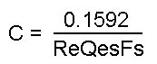
| EQ. 1
C=capacitance in resonance filter
|
|
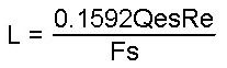
| EQ. 2
L=inductance in resonance filter
|
|
| EQ. 3a, 3b
Resonance equalization
Rc is the series resistance of the
filters
|

|
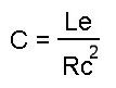
| EQ. 4
Voice Coil reactance equalization
|
|
PHOTO 1
The test setup.
Ignore the component values shown
as they pertain to this speaker. They will, however, give one an idea as to how
high these component values can be.
The two blue capacitors are each
2000uF polarized and wired in series + to - to form a 1000uF non-polarized
capacitor.
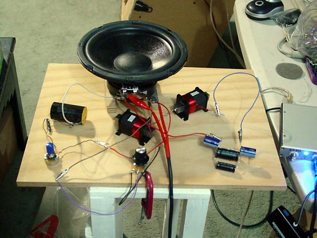
FIGURE 1
This is the open air impedance
response
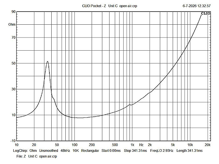
FIGURE 2
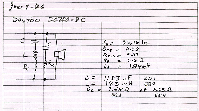
The component values for the CR
filter are 33uF (measured) and 9.2W (measured)
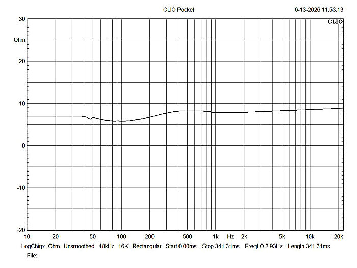
FIGURE 3
This is the equalized impedance
response using both filters. The peak to peak level variation is under 3W.
If you have the time and
patience, by tweeking the values of the CLR filter, it may be possible to raise
the dip below 300hz bringing the overall impedance very close to 8W.
This particular CLR filter in this
example used 18mH instead of the designed 17.3mH. The total measured
capacitance is 1168uF instead of the designed 1183uF and the measured resistance
of the Rc potentiometer is 6W
The component values for the CR
filter in fig.2 are 33uF (measured) and 9.2W (measured)
Back to the
loudspeaker main page