| PHOTO 1
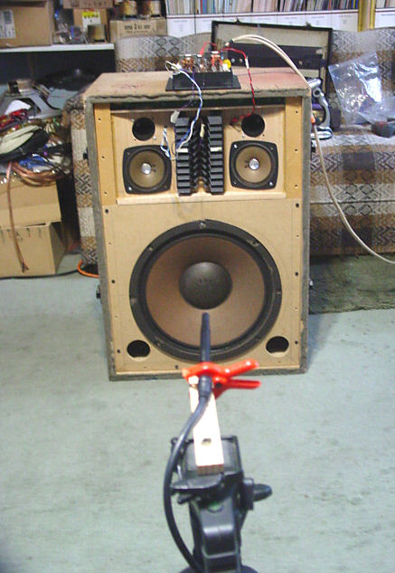
The microphone is looking at the center of the S-106 diffuser (acoustic lens) at the point marked with masking tape. |
|
SANSUI SP-3500 Internal Wiring
| JULY,
2026. An AudioKarma member asked a question regarding the internal
wiring of the Sansui SP-3500 loudspeaker system. Not having such a
diagram, the best alternative was to do that which is shown here. His
question was in reference to the polarity reversal of the S-104 midrange
pair and the S-106 horn, both of which in his pair of speakers were
wired with their polarities reversed.
This was relatively easy to do since a home made SP-3500 is available. To be clear, the only part of the system shown in photo 1 that is not original is the cabinet.
For more on this system, see Sansui SP3500 Odyssey - Addendum This page gives individual Sansui driver data Sansui Driver Data
|
| PHOTO 1
The microphone is looking at the center of the S-106 diffuser (acoustic lens) at the point marked with masking tape. |
|
FIGURE 1
New JIS might refer to Japanese Industrial Standards
.jpg)
|
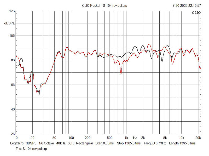
Compare the red curve in the following with the response curve in fig.1 This red curve is the response at 1w1m with all speakers wired in phase FIGURE 2The black curve is that of only the S-104 wired reverse polarity
|
|
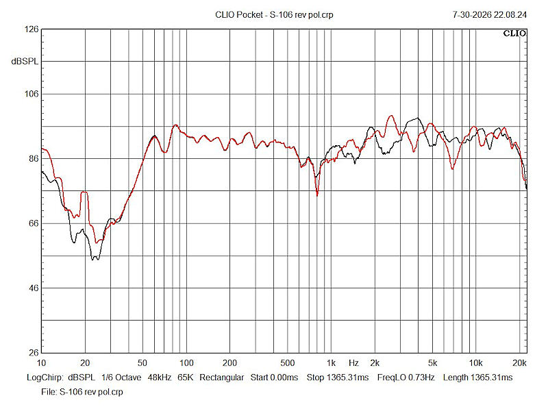
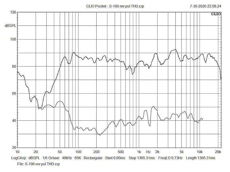
FIGURE 3 The black curve is that of only the S-106 wired reverse polarity
|
|
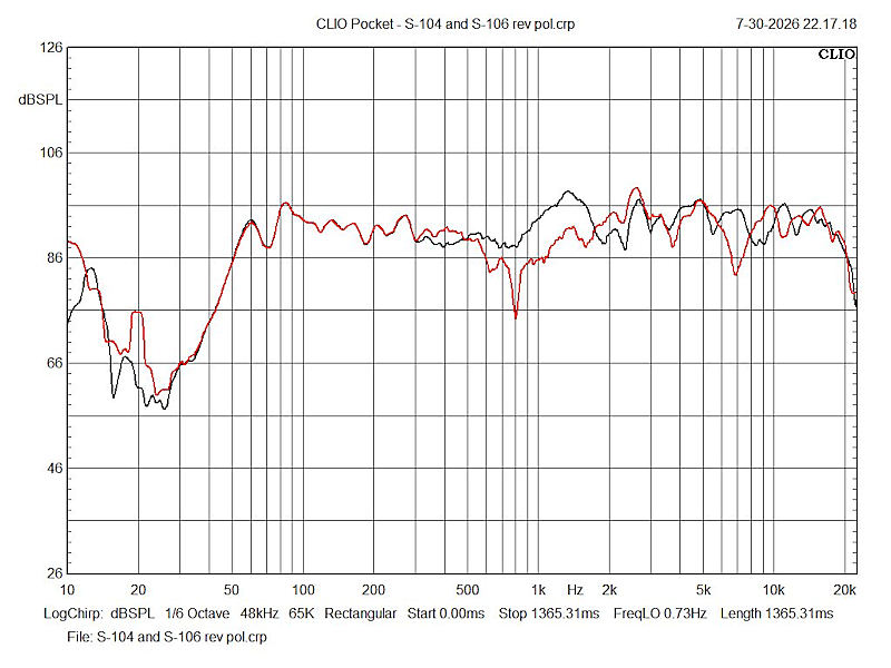
FIGURE 4 The black curve is that of both the S-104 and the S-106 wired reverse polarity
|
|
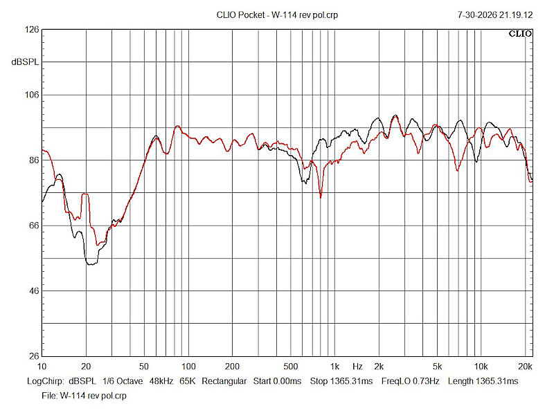
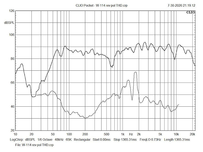
FIGURE 5 These last two were added just for schitts 'n giggles. The black curve is that of only the W-114 wired reverse polarity. In a 3-way with the woofer low pass filtered, the midrange band pass filtered and the tweeter high pass filtered, reversing the polarity of the woofer or the midrange would yield much the same responses. Here, it doesn't because the woofer is not filtered, so its output affects the other three speakers. Theoretically, in this system, reversing the woofer polarity or the polarities of the other three speakers would yield much the same curve. However, theory and practice don't always coincide. In theory, there is no difference between theory and practice. In practice, there is. (Albert Einstein)
|
|
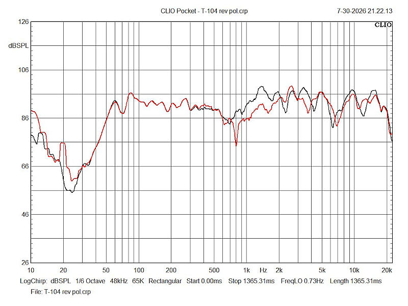
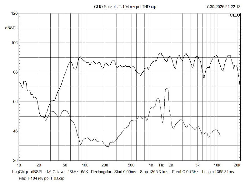
FIGURE 6 The black curve is that of only the T-104 wired reverse polarity
|
EFFECT ON THD
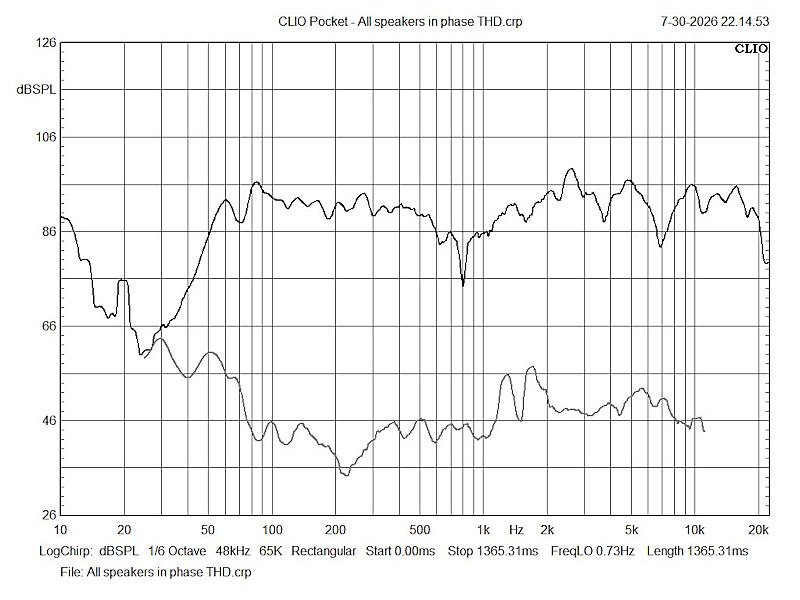
| FIGURE 7
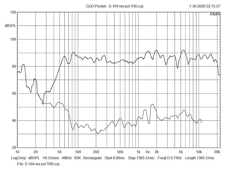
THD, the grey lower curve, averages less than 1% in concurrence with that shown in fig.1, as it does in figs. 8 and 9. But, look at figs. 10 and 11.
|
|
FIGURE 8 The upper curve is that of only the S-104 wired reverse polarity. The lower curve is THD
|
|
FIGURE 9 The upper curve is that of only the S-106 wired reverse polarity. The lower curve is THD
|
|
|
|
The increase in THD in the octave between 1khz and 2khz is likely due to the lack of low pass filtering on the speakers. All but the woofer are high pass filtered only. This allows all speakers to go as high in frequency as possible which can cause the response to become very irregular (see fig.1 and the red curve in figs. 2 through 6. See also fig.12 below.
|
| FIGURE 10
|
|
FIGURE 11
|
|
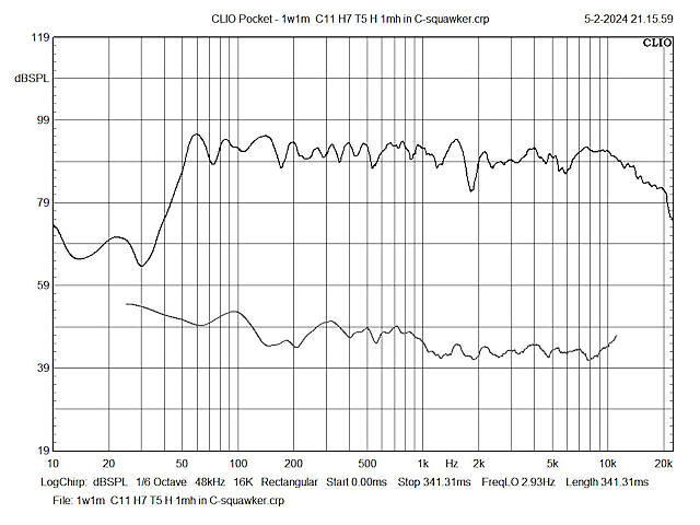
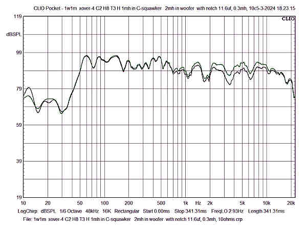
FIGURE 12 This response is that of a newly designed crossover, Xover 5, the attempt being to see how flat a response curve could be obtained. While flat within 10dB (+/-5dB), it isn't as flat as many systems I've designed but it is acceptable and considerably better than the original seen in fig.1 and somewhat better than the subsequent variations.
1w1m C11 H7 T5 H 0.6mh in C-squawker with THD. This was changed from the previous 1.0mh indicated in the graph at the top as the difference was insignificant.
|
|
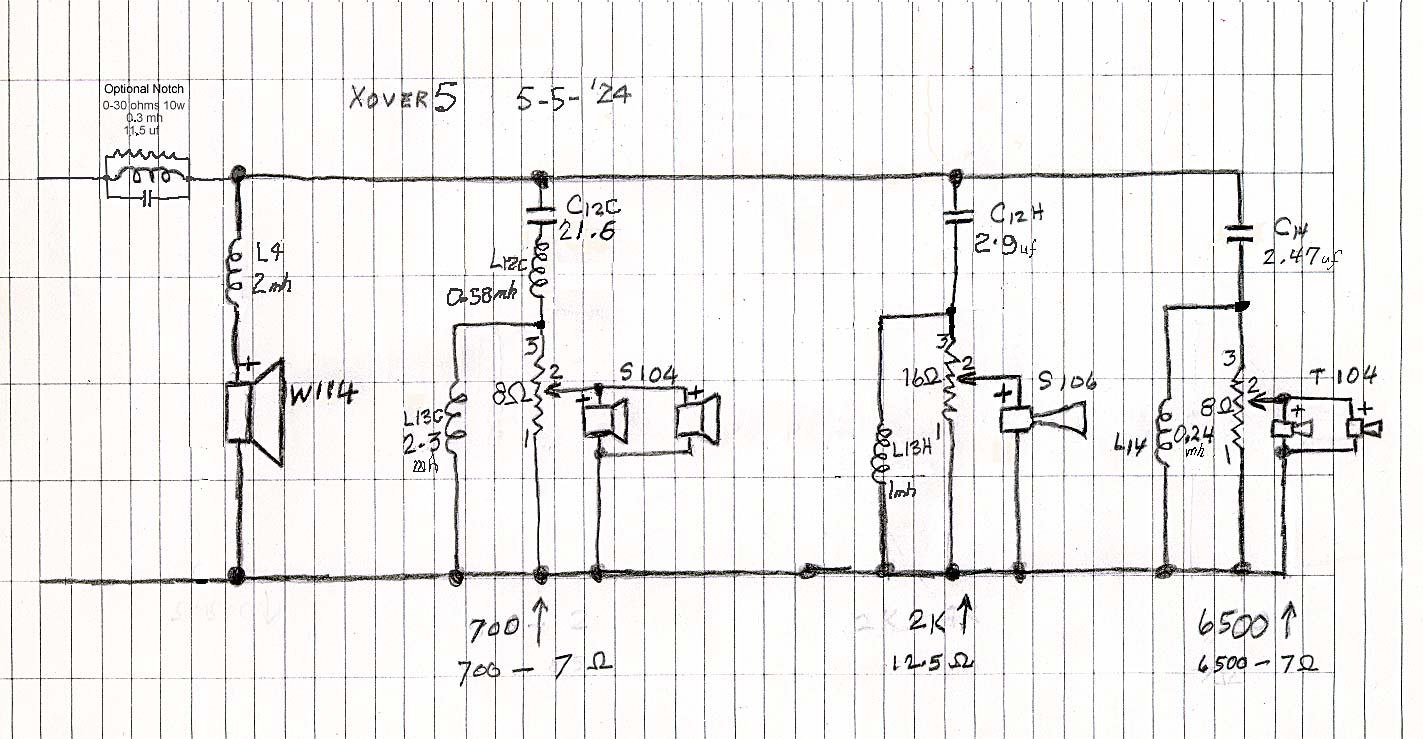
FIGURE 13 The New CROSSOVER - Xover 5 with optional notch filter. the notch filter controls the band covered by both the S-104 parallel pair and the S-106 horn, thus it is placed at the system's input. The other option was to use two different notch filters. Designing passive notch filters with such precision is a difficult task as the component values have to be exact and not as computed by their formulae, but will get one into the ball park. Unfortunately, ball parks are very large, thus trial and error is the result. Click for a larger view.
|
|
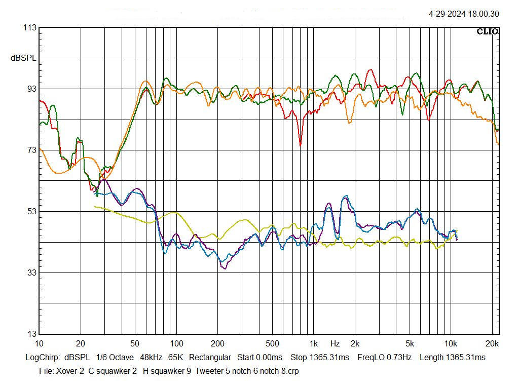
FIGURE 14 1W1M A comparison of the most linear response (green) with the S-104 reversed polarity with the RED, with all speakers in phase with their respective THD responses. RED orig xover All speakers in phase PINK-THD GREEN orig xover S104 rev pol LtBlue-THD ORANGE Xover-5 C11 H7 T5 NO NOTCH YELLOW-THD NOTE: C11 is the L-pad for the cone mids (S-104) turned to 11 o'clock; H7 is the L-pad for the S-106 horn turned to 7 o'clock; T5 is the L-pad for the T-104 tweeters turned to 5 o'clock Note also the reduction of THD above 1khz with Xover 5. It's about 0.7% less.
|
|
FIGURE 15 This shows the effect of the notch filter (black, lower curve) and without the notch filter (green, upper curve). The attenuation between 700hz and 2khz -is about -2dB, from 2khz to 5khz it's about -5dB and from 5khz to 10khz, -2dB
|
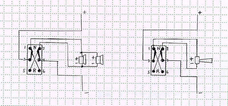
A 'NOT SO IMPORTANT' NOTE This may seem to be more trouble than it's worth, unless you're one who likes details. It is not intend for those not into that which may be referred to by many as overkill. Then there's the cost of the wire and switches unless one has them in their stash. Anyway, for the curious, here goes. The following schematic shows two DPDT (double pole, double throw) switches. One is wired into the S-104 parallel pair and the other into the S-106 horn. Their purpose is to reverse the polarities of each speaker section independently or simultaneously, thus giving three options. The switches are wired in series with the main input line to the respective speakers. Any parallel components wired to the speakers will be maintained. Each switch is initially wired with pins 1 and 6 together and pins 2 and 5 together, as shown in the 'X' in the switches. The 'N' and 'R' refer to normal and reverse polarities. The wire can be AWG20 or AWG22, solid or stranded. Solid may be easier to insert into the holes in the switch terminals. Stranded will require tinning which will increase the wire diameter. However, stranded will provide a more flexible line from the crossover to the operator. This line should be at least 10 feet so the operator (listener) can be seated or standing at least 7 feet from the speaker system. If AWG20 wire is used, the additional wire resistance (impedance) will increase by 0.2W and if AWG22 wire is used, this increase will be 0.32W. Neither will cause noticeable insertion loss with music; it's about 0.2847dB with 20AWG wire and 0.4515dB with AWG22 wire. A good set of ears may hear that subtle difference with a single tone applied to the speaker but not with music as the level is in continuous amplitude and frequency variation. With the pair of switches taped together and properly oriented, the polarities can be reversed simultaneously very easily.
FIGURE 16
It should be noted that the practicality of the above may be questionable. The switches will cost about $4 each and the wire about $11, plus the shipping which could bring the total cost close to $30.
|
Back to the loudspeaker main page