SCOTT MODEL 99-B
Herman Hosmer Scott, (1909-1975) aka H.H.Scott
| I found this
unit on the bay and couldn't
resist. It dates to 1954. It's rated at 22 watts but the
best I can get is about 9 watts to 17 watts between 30hz and 20khz, the
lower power at the lower frequencies.. All tubes were replaced as
well as power supply caps and several others in the circuit, notably the
black "bumblebee'" caps which, as I read on a few audio sites,
will fail internally. According to some, the ESR can rise so high
as to make the cap behave much like a resistor. Some did have very
high ESR and their capacitances varied widely from specification.
For example, C25 (0.022uf) measured 0.041uf. C22 (0.0047uf)
measured 0.0084uf
and C17 (0.047uf) measured 0.073.
Once the caps were opened on one end and the tubes removed, several resistors were easily checked and found to be OK. The others will have to be checked by lifting one end to isolate it. Resistors R42 to R47 measure well within a 10% tolerance. The power supply delivers 388vdc at pin 2 of the 5U4. The voltages present at the capacitors moving left from the tube and through the resistors are 378, 359, 321 and 229 vdc. All are well below the 500 volt rating of the new filter caps. The transformer delivers 360-0-360 vac with 120vac line. Building another supply and using a variable transformer, higher voltages can be obtained. The original filter caps are rated at 475vdc. The caps ratings are 25% higher than the highest available dc voltage. It was suggested to use a variable transformer at the line and crank the 120vac but that doesn't seem advisable considering the age of the original power transformer. The line would have to be taken to around 135vac to get the dc voltage at the 5U4 pin 2 higher. There's more on this at the bottom of this page, photos 5 & 6. Doubling the capacitances of the power supply capacitors made little to no improvement on power output. Going higher would increase the inrush current and load the rectifier tube and the power transformer. I built the wood cabinet. Nothing fancy but at least the amp isn't naked. |
PHOTO 1
PHOTO 2
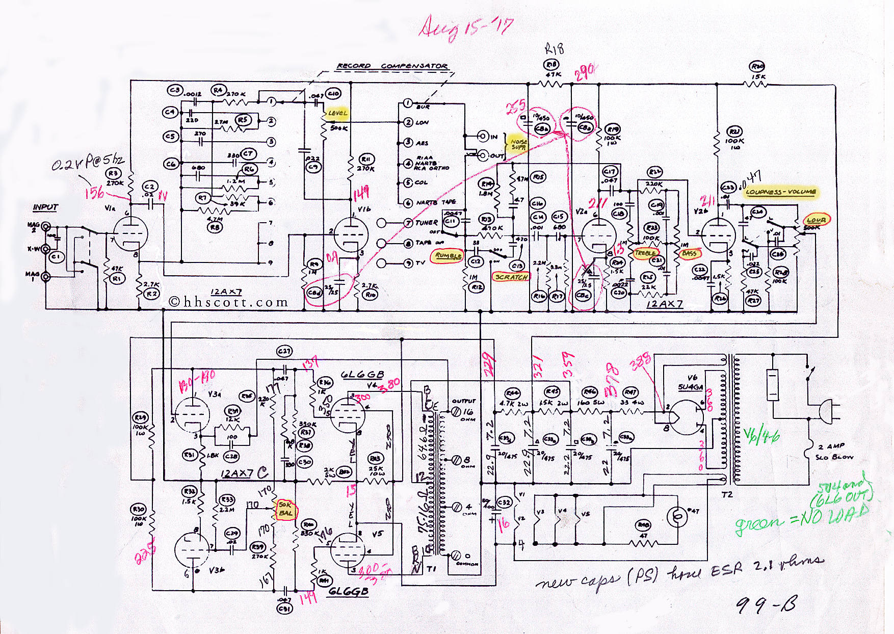
The seller said that the LEVEL control on the left didn't work but it does. One has to see the schematic to see why. Refer to FIG. 1

PHOTO 3

|
PHOTO 4 Two of the "bumblebee" caps have yet to be replaced as I couldn't obtain the correct values. When those are obtained, I'll probably replace all the resistors also The brown cap in the center, C32 will also have to be replaced but couldn't find a 50uf/100v or close anywhere. There's also what appears to be a 50k bias pot, called a balance in the schematic. (fig.1A, lower left corner) It seems to balance the bias of tubes V3a and V3b which, in turn, drive the output tubes, V4 and V5. An imbalance here may cause a loss of power output, a non-symmetrical waveform at the output and distortion. The voltages on each end of that balance pot are 170vdc. On the outer ends of R35 and R39, the voltages are 167vdc and 177vdc, resp. This might indicate either a bad R35, R39 and/or bad C27, C31. The voltages differ considerably but not knowing specification, I can only guess. It could be normal as there isn't any non-symmetry in the waveform at low frequencies. (See photo 6) In short, all components associated directly with the 6L6 output tubes will have to be checked. This will be done when I have replacements. Not being an engineer or experienced tech, I have to proceed with caution. The four blue caps are those of the power supply. 20uf each at 500vdc
|
 |
|
FIG. 1 The LEVEL control is at C. It works only in the PHONO mode. Positions 1 thru 6 are for EUR, LON, AES, RIAA, COL and NARTB TAPE. (National Association of Radio and Television Broadcasters). In positions 7, 8 and 9, all the circuitry in the upper left corner and the LEVEL control are bypassed. The level control is to adjust/compensate for the different output levels of various phonograph cartridges. Click the image for a larger pdf format
FIG. 1A AN AFTERTHOUGHT This image has recorded voltages from my working unit as well as the controls being highlighted in yellow. These voltages are not absolute as the circuit tolerances for voltages, resistances and capacitances are +/- 15%] Click the image for a larger format |
|
|
FIG. 2 This widget is a dynamic noise suppressor. It suppressed record noises, nics and pops from playing 78 rpm records. It was connected to the jacks A and B on top of the 99-B chassis (in fig.1) Note that the jack at B (in fig.1) is a switch. When the input of the 111-B is plugged into A, the signal is routed through the noise suppressor, the output of which is fed back into the 99B at B. It seems that Mr. Scott was a couple of decades ahead of his time. A link to a better description was here but now, it's gone. http://hhscott.com/cc/dynaural_noise_supressor.htm I don't have this unit but after the amplifier is working satisfactorily, I just might look for one or maybe even build one just for the fun of it. |
|
| FIG. 3
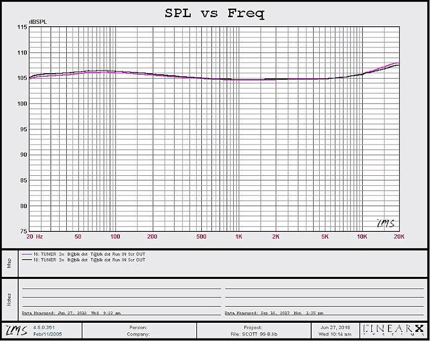
The black and pink traces are obtained under identical conditions but 9 months apart. Tuner input, bass & treble controls@ 0, Volume/Loudness switch @ Volume, Rumble & Scratch filters OFF. The left scale is 1dB per sub-division. The slight rise in the treble above 7khz is negligible, being only +3dB at 20khz, probably a benefit for aged ears. Lowering the treble control more results in a decrease in output above 1khz.
|
|
| FIG. 4
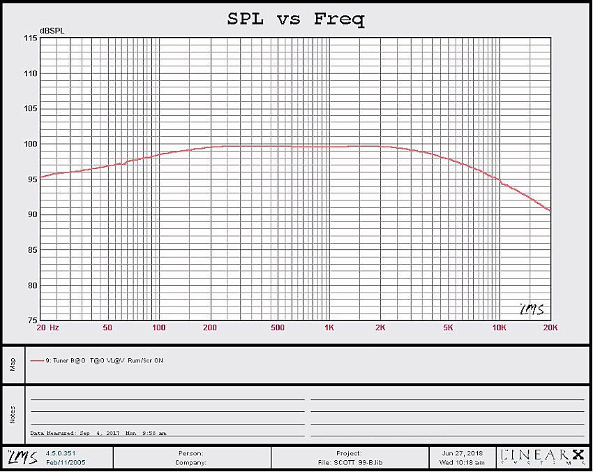
The orange trace shows the effect of the rumble and scratch filters. |
|
| FIG. 5
The various recording compensation EQ's all of which have been standardized to the RIAA curve (dark blue). How much these deviate from the ideal is unknown. Trace #14, the EUR 78 is the exception and may be correct, according to that which I found in the following link regarding European 78 recording eq. in the thirties and forties. According to the first two entries listed in Table 1 in the following link, the EUR EQ circuit is working right. https://wiki.audacityteam.org/wiki/78rpm_playback_curves This page was created and uploaded in 2020. Upon finding the Scott thread on AK, the above link was checked and found to be no longer in existence. To quote the title of a 1958 song by Buddy Holly, "(I guess) It Doesn't Matter Anymore" |
|
TABLE 1
Equipment used. Tektronix AA501 distortion analyzer and Tektronix FG-502 function genny which has 0.5% THD, so subtract that from the figures below.
| THD + noise relative to 2w @ 1khz into 16 ohms (resistive) | ||
| f (hz) | THD+noise (%) | Output Relative to 1khz (dB) |
| 30 | 2.22 | 0.5 |
| 50 | 1.44 | 0.8 |
| 100 | 1.74 | 3.8 |
| 1k | 1.80 | 0 |
| 5k | 1.48 | 1.6 |
| 10k | 1.47 | 2.0 |
| 15k | 1.49 | 2.0 |
| 20k | 1.44 | 2.5 |
TABLE 2
| THD + noise @ full power into 16 ohms (resistive) | |||
| f(hz) | THD + noise (%) | Output relative to 1khz (dB) | Power (W) |
| at the visible point of clipping seen on scope Tektronix 465, an oldie | |||
| 30 | 5.25 | 0.2 | 9.47 |
| 50 | 4.16 | 0 | 11.82 |
| 100 | 4.27 | 0.1 | 10.18 |
| 1k | 5.49 | 0 | 9.9 |
| 5k | 6.44 | 0.4 | 10.92 |
| 10k | 6.59 | 1.4 | 13.88 |
| 15k | 7.9 | 2.2 | 16.4 |
| 20k | 8.0 | 2.5 | 17.39 |
| PHOTO
5
This is a 50hz signal The line voltage has been taken to 135vac. The output of the power transformer is 400-0-400vac and that of the 5U4 pin 2 is 441vdc. This produced 17.41vrms across the 16 ohms resistive load for a power output of 19 watts.
|
|
| PHOTO
6
This photo shows the waveform at the load resistor after the AC line was dropped to 120vac. Nothing else was changed. The waveform is highly distorted. When the amplifier volume control was lowered to produce a clean waveform, the output power dropped to 15.8 watts. Not knowing the conditions under which the 22 watts was achieved and not knowing the voltages at various points in the original design leaves one in the dark, so to speak. At least the waveforms are symmetrical with respect to amplitude. |
|
|
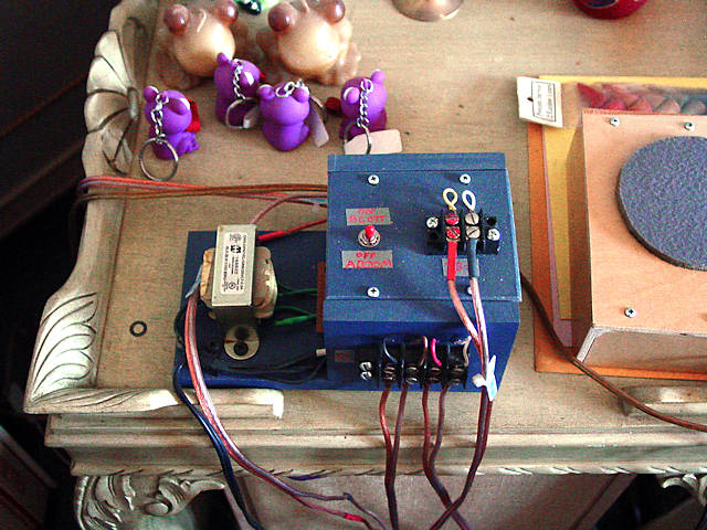
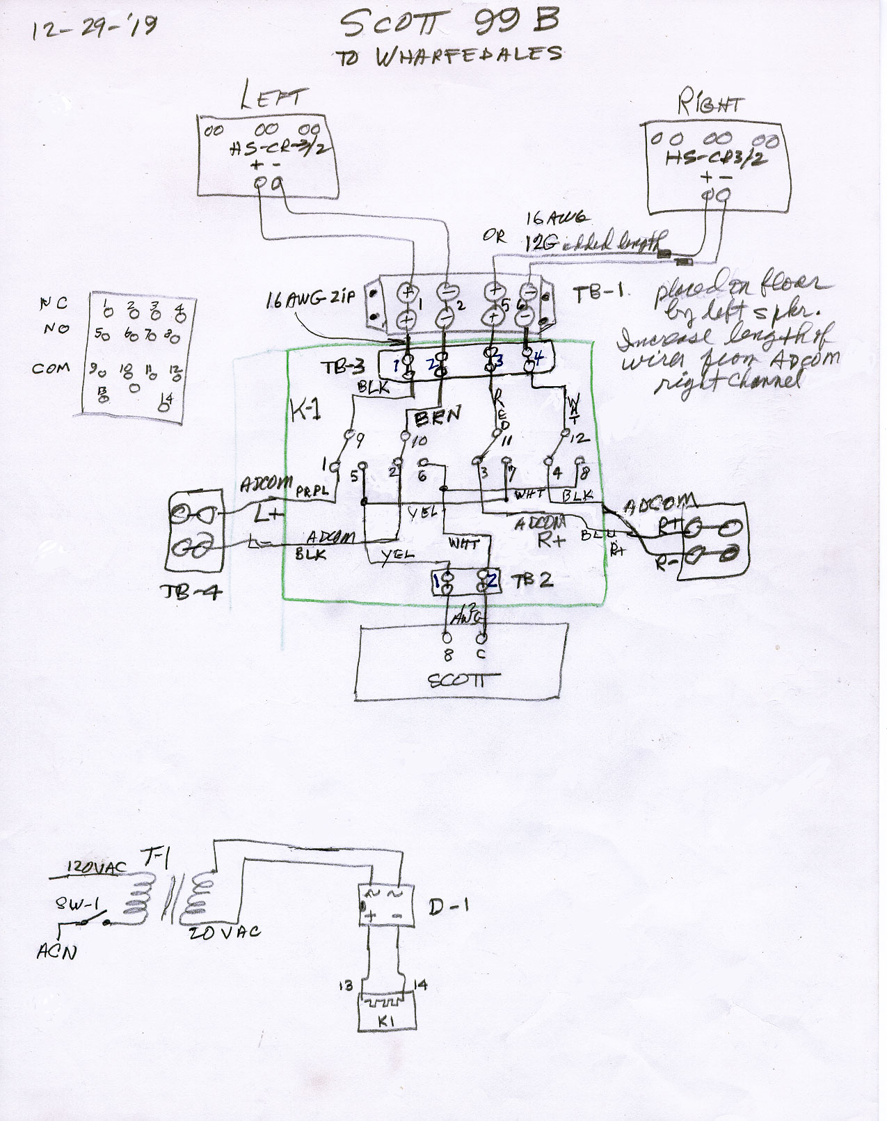
The Switching Box PHOTO 7
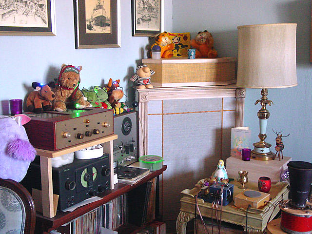
PHOTO 8 The Left Corner The Scott above a Hallicrafter short wave-long wave receiver. The corner speaker system is described by the bottom photo HERE
|
| FIG. 5
How it works. The Tuner input of the Scott preamp is connected to the Phones output of the Adcom preamp. The Adcom tone controls are bypassed and the preamp is set to mono if a stereo source is played. The speakers are connected through the switching circuit which, when ON, will switch the speakers from the left and right outputs of the Adcom power amplifier to the mono output of the Scott. These speakers are 8W each so, when paralleled, they are connected to the 4W output of the Scott. The volume levels are adjusted for equal levels from both amplifiers. Once achieved, it's extremely difficult to determine which of the two amplifiers is driving the speakers. Click the image for a larger view |
|
Back to the loudspeaker main page