| On
many occasions, the question of crossover component tolerances has been
discussed. Many of these discussions wander around aimlessly as
very few even touch on the importance of the actual impedance of the
speaker at the crossover frequency. This discussion, hopefully, will
shed some light on that topic. It will show that the driver
impedance at the crossover frequency , if incorrectly assumed, will
create a larger problem than the tolerance of the components used.
In all fairness, it must be stated that these errors, however induced, may or may not make much of an audible difference. However, that may be open for debate and in my experience, it sure seems to make the aforementioned audible difference. Again, how important that audible difference may be can only be evaluated by the listener. In short, if the listener like what is heard, does the above really matter? Consider the following example, a system I designed many years ago with a friend. Two such systems can be seen HERE, the one referred to above being the top unit in that page. In the mid nineties, that unit was preferred by the owner of a set of $3000 speakers very similar to mine, close to $5000 in 2018. Supposedly having golden ears and being a sales person for high end speakers, his claim was that on his speakers he could differentiate the mid-range and tweeter while mine had a point source, meaning the two upper register speakers appeared as one. That was, IMHO, the result of carefully measuring component values and calculating those values at the impedance of the speakers at the crossover frequency. The only other difference was that my eights didn't have the bass output of his tens, which is understandable but a slight bass boost made short order of that. His other praise was that the stereo image locked in as with some speakers, the image seems to wander between left and right and can be very noticeable on vocals. This happens as the vocalist's voice changes pitch. That reference to the wandering voice does not apply to such live recorded performances where the singer may be moving around the stage. However, if the singer is using a mic, their voice will always appear as coming from a fixed location, unless, of course, the recording engineer pans that track to follow the singer. Such critical listening makes me wonder about that to which the listener is listening; the speakers or the music. Of course, one would also have to be in the so called 'sweet spot'. The following schematic shows only the mid-section of a second order three way crossover. The crossover frequencies, f1 and f2 are 500hz and 5000hz. I like decades. The rated impedance of the drivers is 8Ω.
FIG. 1
I'll work on the capacitors first as they have a wider tolerance than coils. Capacitors come in 1%, 2%, 5% and 10%. Let's consider the extremes, 1% and 10%. Usually, if the tolerance isn't marked on the capacitor, it a good bet it's 10% or higher. Also considered is the assumed impedance of the speaker. For a woofer, the stated impedance will be close to the actual impedance, as long as the crossover frequency is between 250hz and 500hz. Below 250hz, we approach the upper bound of the resonant frequency band, which, if narrow will have little effect but if wide, can be higher than the rated impedance. This usually won't have much effect as most of the action comes from the mid-range. Now, the mid-range unit. If the mid-range is a true mid-range design, it will usually have a linear impedance in the lower range but this may not necessarily be true for the upper range. Some more expensive mid-range units have a very linear impedance. A mid-bass unit will usually have a much higher impedance at the high end of its pass band than at the lower end. Typical mid-range units will have a substantial rise in impedance around 4khz. In this discussion, a Fountek FW146 is used, which is rated as 8Ω but in reality is 7.4Ω at 500hz and 10.6Ω at 5000hz. If 8 ohms is assumed across the band, the crossover doesn't function as intended at 5000hz. All right, first the capacitor tolerance and an assumed 8Ω across the band.
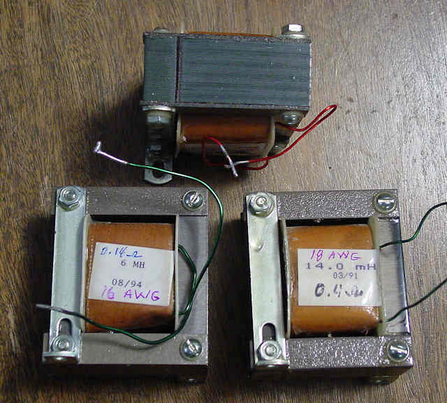
At the lower end of the band, the 0.6Ω difference between measured and rated impedance is negligible, if one uses a 1% or 2% cap. Using 10%, the crossover frequency point will range anywhere from 562hz to 454hz and with a 5%, from 529hz to 478hz. However, using a 1% or 2% cap, the crossover point will be within +/- 5hz. Not a problem at this end but a different thing at the upper bound where the incorrect impedance can wreak havoc on the crossover point, the KNEE, which is the point where the output drops by -3dB. At the upper bound of the mid-range pass band, the impedance is 10.6Ω. Assuming 8Ω, a cap of 2.8uf is required. But, when this cap is applied to a load impedance of 10.6Ω, the knee occurs at 3792hz and that's assuming a 1% or 2% cap. A 5% cap will set the knee anywhere from 3991 hz to 3661hz, neither of these being anywhere near the desired 5000hz. Since tweeters usually have a linear impedance very close to their rated impedance, a dip in the response around 3991hz and 3661hz will result due to the tweeter not coming in fully until about 5000hz. If one gets lucky and isn't using a Butterworth filter design which has a very flat response at the knee, the resultant response can possibly be flat. This is because some filters have a slight rise at the crossover point. The Butterworth is quite flat and without ringing (ripple) at the knee but at the cost of slight loss in transient response. Generally speaking, the Butterworth is considered by many to be the best of compromises. Using the correct impedance of the driver at the crossover point, 10.6Ω, requires a 2.12uf cap. A 5% tolerance cap will result in the knee being anywhere from 5256hz to 4782hz while a 1% cap will get you within 4933hz and 5085hz. A lot of manufacturers publish impedance curves. It would behoove the designer to use it. And now for something completely different, the coils. Much the same logic applies here. However, if one has an inductance meter, one can use a coil slightly larger than required and simply unwind a turn or more to obtain a closer value. This isn't as critical as the capacitors values because most coils are very close to their rated inductance. Keep in mind that the inductance of the driver's voice coil should be deducted from the crossover coil(s) that are in series with the driver. Those in parallel will have negligible effect. The dcr is important, the lower, the better but also more expensive due to a thicker wire and as a result, physically larger. Iron core coils can be used but they will saturate sooner at higher power levels. Laminated cores are better yet; some such inductors physically resemble a transformer. FIG. 2. FIG. 2
Ferrite bobbins are ok at low power levels but that core behaves much like a one turn winding of very low resistance. It'll behave like a shorted secondary on a transformer. At high power levels, this ferrite bobbin can heat up.
|