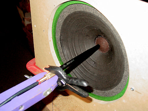
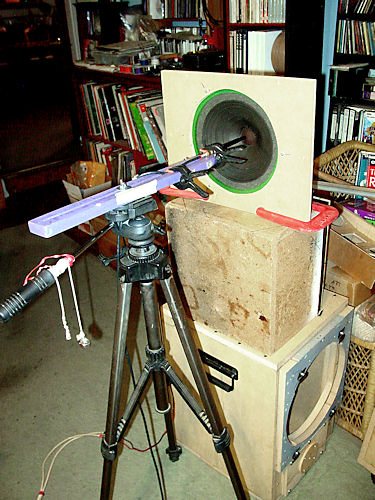
| The
testing apparatus
Photo 1
|
Photo
2
|
How A 12" Speaker Reproduces High Frequencies
| Ever
wonder how a large speaker can work as a full range up to about 10khz,
maybe higher? The following is a S.W.A.G. (Scientific Wild Ass Guess) at
explaining that.
The math behind most engineering explanations dictate that such a speaker cannot do that; cone mass and voice coil inductance being major premeditated factors. These all make the assumption that the cone is perfectly rigid and acts like a piston; it moves forward and backward or up and down as a unit, much like the piston in an internal combustion engine. Unfortunately, speaker cones are not rigid. They react to the forces exerted upon them by the voice coil in various ways, depending on their mass, density and density variations. In a perfectly rigid cone, the cone mass would attenuate the frequency band below about 600hz at a rate of 6dB/octave. next would be the effect of voice coil inductance at a slightly higher frequency and at another 6dB/octave. Last would be the front cavity compliance, which would be the volume of air in the cone itself. For a direct radiator, this would be negligible but in a horn where the throat area can be half that of the effective cone area which would attenuate the higher frequencies at a rate of 6dB/octave. In a horn, these frequency points can be around 400hz, 600hz and 2400hz. Fortunately, loudspeakers are not perfect and this works to out advantage in some ways. It can boggle one's imagination how such a simple device like a loudspeaker can do so wee reproducing the sound of a 100 piece symphony orchestra when, in reality, the loudspeaker doesn't resemble any instrument with exception of a drum..
|
| The
testing apparatus
Photo 1
|
Photo
2
|
|
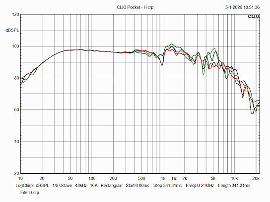
From a paper submitted to the A.E.S. by Don Keele in May of 1977, the following relationships are found. First, a description of the nomenclature. Fs driver resonant frequency in open air Fhm the driver's moving mass corner, the primary effect Fhvc the driver voice coil inductance corner, the secondary effect. There is a tertiary effect due to the air load in the cone cavity but it's very small. B2L2 BL product squared = (BL)2 (B=gap flux density, in Teslas; L=length of the voice coil wire, in Meters) Mmd diaphragm mass, in kilograms (MKS system) excluding the loads imposed by the air, spider and annulus. (moving system mass. Mms, not used here includes the effect of those three loads.) Re and Le are the voice coil dc resistance and inductance, resp. in ohms and henries (MKS system 1H = 1000mh 1mh = 0.001H) Now, the mass corner (at -3dB), is given by Fhm = (BL)2/p/ Re/ Mmd and is also given by 2Fs/Qts using the T-S parameters. (Eq 1a and 1b) The voice coil inductance corner is given by Fhvc = Re/p/Le and in T-S parameters is the same. (Eq 2) Now, for moving mass corner of the B209A, we have Fs = 202 and Qts = 1.469 giving an Fhm = 242hz. (Its inductance is 0.000519H) So, due to cone mass alone, the response should fall at a rate of 6dB per octave after 242hz. As can be seen by the response curves, it doesn't. Add to that the effect of voice coil inductance, Fhvc. Using eq 2, we get 7118hz. This is a much lesser effect.
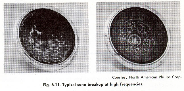
The question now is how does this driver do so well up to 12khz? Quite simply put, traverse waves through the cone material. As the voice coil moves forward and backward, ripples are formed in the cone much like the hump in a rope on the ground when one end is whipped by hand. These traverse waves will move faster than sound waves in air due to the denser material and considering the density of aluminum, the speed of sound is a whopping 5000 m/s, 14.5 times faster than through air. When these waves get to the circumference, a reflection occurs and this exacerbates cone breakup at higher frequencies. See photo 3 below. If the cone were perfectly rigid and acted like a true piston, traverse waves would no longer exist and any damping material on the cone would not be necessary. The damping material on the cone will suppress ringing but will not completely stop it. The cone is flexible and only a perfectly rigid material will work. Some manufacturers have used sandwich cones, made of three materials. The two outer layers are usually Kevlar® and carbon graphite on each side of a lightweight but very rigid honeycombed layer. ETON of Germany comes to mind with their Hexacone® series. Unfortunately, they no longer make true midrange Hexacone® drivers; all are bass-midrange.
Photo 3
|
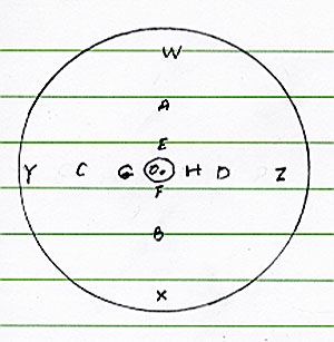
The following is another SWAG regarding cone breakup. This should explain why near field responses are good only below about 400hz. This analysis looks at 12 spots on the cone, located at 12 o'clock, 3 o'clock, six o'clock and 9 o'clock. In groups of four, they are spaced radially from the center to the circumference. Three more are measured at the center, but at different distances from the center of the dustcap. All the others are measured at roughly 3mm from the surface of the cone.
|
| Figure
1
The microphone location points. O is at the center of the dustcap. E, F, G and H are just outside the circumference of the dustcap. A, B, C, and D are midway radially from the center and W, X, Y and Z are at 1/2 inch inside the circumference. With exception of those at O, all are 3mm from the cone's surface. |
|
|
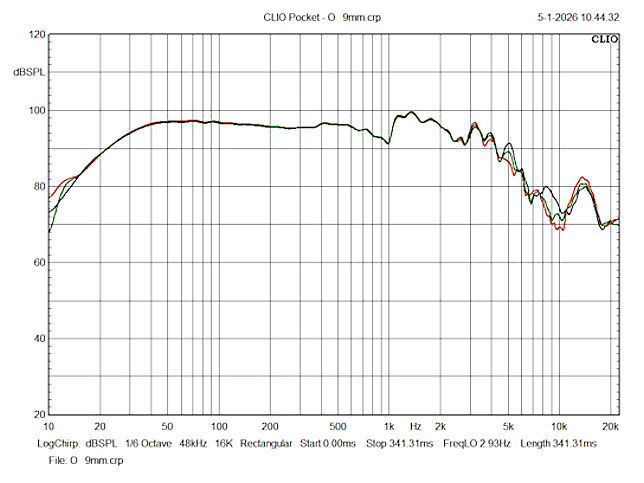
Figure 2
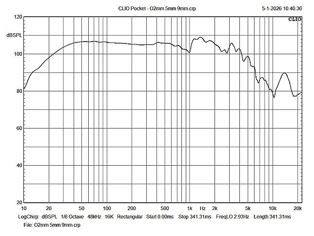
This shows the three responses taken at point O but at increasing distances from the dustcap. RED-2mm, GREEN-5mm and BLACK-9mm All are at much the same level of intensity despite the 6dB loss when doubling the distance. This is due to the pressure being very close to equal within the frustum of the cone although it does decrease slightly at increasing distance from the apex.
Figure 3 This curve is the sum of the above three. the increase in level is due to my forgetting to normalize the level. At any rate, it's very similar to the curves of fig.2. The bump around 14khz is interesting and is explained below.
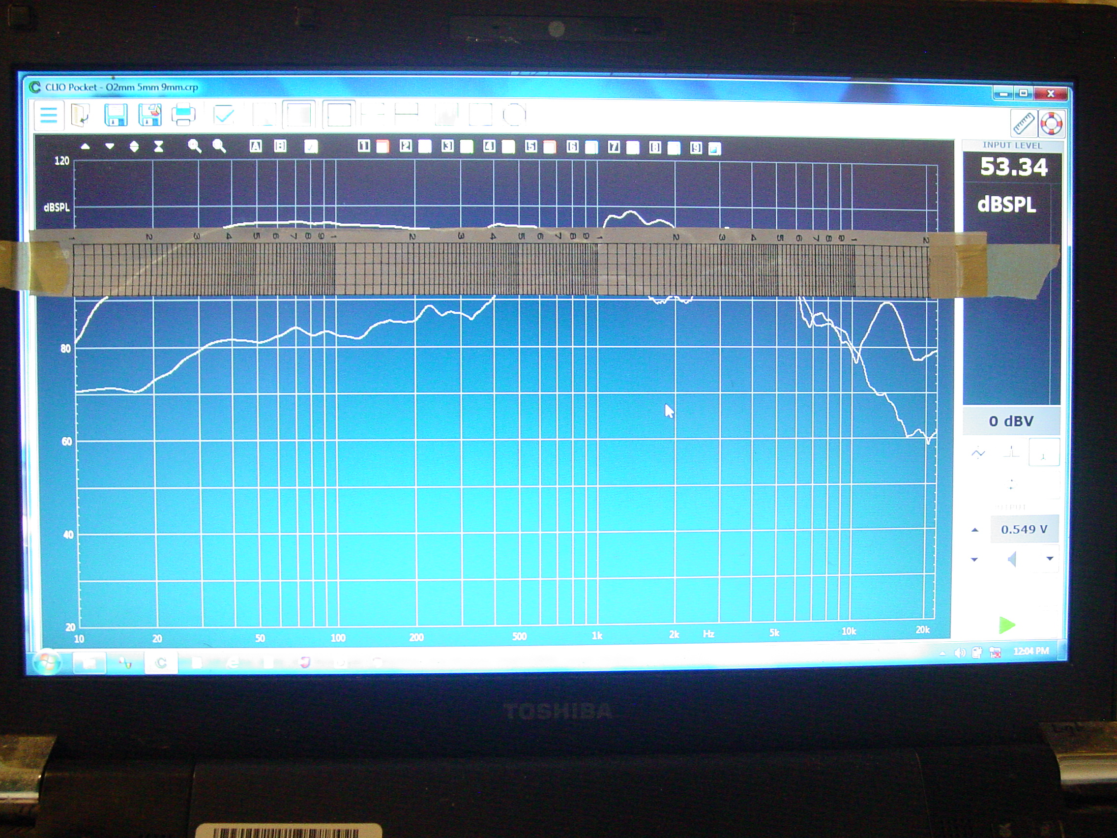
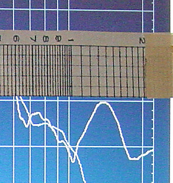
Figure 4 This is a photo of the computer screen. The Pocket Clio doesn't have a cursor to move along a response curve to note the parameter at that point. So, I scaled a 3 cycle log paper to fit the screen. It shows the peak around 14khz. An enlargement of that bump is shown below, in fig.5 click for larger image
Figure 5 The bump peaks between 13khz and 14khz. Now, the speaker has a voice coil diameter of one inch. This just happens to coincide with the wavelength of a 13.6khz frequency. The speed of sound, corrected for 76oF is 13.608 ips. (345.6m/sec)
|
| These
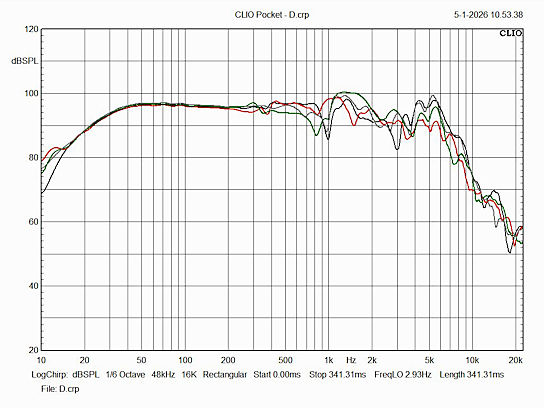
two figures, 6 and 7 show all the curves taken at the indicated points.
The points A, B, C and D are farther from the apex than the points E, F,
G and H, hence the high frequency
attenuation above 6khz due to the damping effect of the cone material.
This seems to be somewhere around the point of maximum high frequency
attenuation. The next figure, fig. 8, shows a little more attenuation
above 15khz.
|
|
|
Figure 6
RED-A GREEN-B GREY-C BLACK-D
|
Figure 7
RED-E GREEN-F GREY-G BLACK-H
|
|
Figure 8
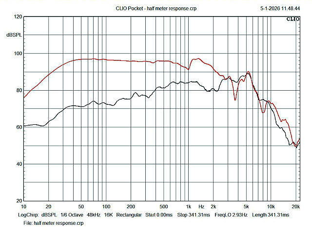
This compares the sum of the near field responses, A through H and W through Z (RED) and the half meter response (BLACK). Both show an additional 5dB to 6dB attenuation above about 15khz. The frequency attenuation below 2.5khz is due mostly to the front to rear cancellation due to the small dimensions of the baffle. This attenuation is not seen in the near field response, (RED), due to the proximity of the mic to the cone.
|
RED- Near Fields A-H W-Z BLACK half meter
|
Figures 8a (left) and 8b
(right)
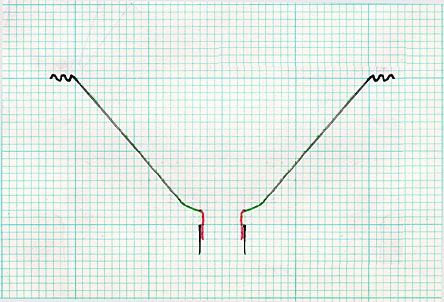
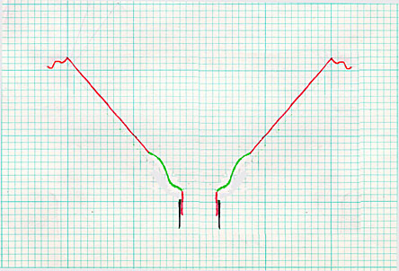
When the voice coil moves forward, the cone ripples at the apex. This is due to the cone's moment of inertia. (8a) When the voice coil reverses direction and moves inward, the opposite happens. Meanwhile, the initial ripple is moving towards the annulus at a few or more thousand feet per second, depending on the material of the cone. In aluminum, it would move at about 5000m/sec, (16,000 feet/sec). As the voice coil oscillates, the green part of fig.8b moves toward the annulus, with decreasing amplitude. It much like taking one end of a rope laying on the ground and oscillating that end. A hump will move along the rope At a rate of three times the speed of sound in air, roughly 41,000 ips, it would take 0.12 m/sec to travel the 5 inches from the apex to the annulus. There isn't much point to making actual calculations as to how many pulses (ripples) would be present at any frequency. At, say, 5khz, with a pulse duration of 0.2 m/sec and a wavelength of 2.7 inches, there would be two complete cycles between the apex and the annulus. This pulse would also decrease in amplitude as it moves to the annulus, thus decreasing the amplitude of the reflection. Now, consider how the signal varies with music , not only in frequency but also in amplitude. Thinking about that will surely keep one awake at night and during then day can likely induce a headache. Photo 3 (above) shows cone breakup and likely at one frequency.
|
Back to the loudspeaker main page