More on Potentiometers to Attenuate a Loudspeaker
and some of the effects on impedance and crossover point
An addendum to an earlier page
This work stemmed from the repair of a Wharfedale crossover dating to the late 50's. L-pad, potentiometer or series resistor. All have their good and bad points. By far, the best option is to select the drivers carefully so as to match their efficiencies, therefore eliminating the need of an attenuator. However, sometimes the listener prefers different settings of the mid-range and tweeter depending on the type of music If that be the case, the best choice is the L-pad as it has little and the least effect on the load impedance. An L-pad can also be made with two fixed resistors but this eliminates any further adjustment. The fixed series resistor will be discussed next as it's the easier of the remaining two choices. Consider a resistor of 10 ohms in series with a 15 ohm tweeter and 2v applied. Initially, it looks simple but many, if not most, will insert the resistor AFTER the crossover is designed. This is not good and for the following reason, a shift in the design crossover frequency by about 50% lower. 
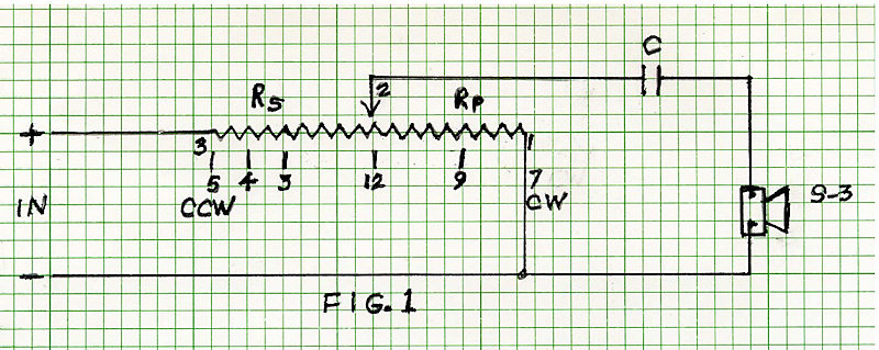
With an impedance of 11.4 ohms and for a first order filter, a 2.8 uf capacitor is required. The closest standard value would be 3 uf. With a 3uf cap, the crossover knee (-3dB down point) is 4656hz. Now, insert the 10 ohms attenuator and the load impedance jumps to 21.4 ohms, resulting in a knee at 2480hz. The resultant attenuation is -5.46 dB. With a tweeter capable of 92dB 1w-1m, this would bring it down to 86.5dB which is not really an 'easy listening' level. So, the shift in crossover frequency is of no consequence unless the listener 'pours the coals' into the speakers. With as little as 2v into the tweeter, the resistor will dissipate 0.0874W and the tweeter, 0.0997W. (rounded to 0.1W). This is 10dB below 1W, or 82 dB with this tweeter. Without the 10 ohms series resistor, that same 2v would drive the tweeter to 87.4dB and it would dissipate 0.354w. To maintain the correct crossover frequency of 5khz with the 10 ohms series resistor, the filter has to be re-calculated for a load impedance of 21.4 ohms, not 11.4. This would require a capacitor of 1.488uF (1.5uf). With the resistor and a 10dB rise in power output, the tweeter would now have to handle 1W which it can easily do but with that resistor and no correction of the filter cap, the tweeter will be delivering 86dB at5 2380hz. It's 6dB down due to the first order filter or 1 watt. Now, that may still be harmless with most music but if there's any percussion, like drums and cymbals or a hard 'rim shot' on a snare drum, the fragile voice coil of the tweeter can easily shatter or unwind. This can happen very easily to a self supporting voice coil, i.e., no coil form, like the Electro-Voice T35, used in the Klipschorn®. Despite it's 104dB at 1 watt, and a second order filter at 5khz, Klipsch later installed back to back 10W zener diodes across the tweeter to protect it. 'Nuff said on that. No further discussion on the L-pad appears to be needed as the biggest problem with them is the possibility of their becoming intermittent if not of good quality. This potential 
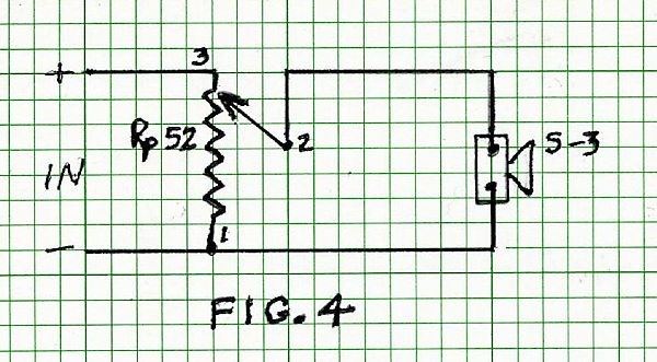
problem exists with the potentiometer, along with others discussed below. The potentiometer was used extensively in the 40's through the 60's and maybe later in less expensive systems as they are considerably less expensive than L-pads.
|
PHOTO
1
The pot used here, a Honeywell 53C350. It's wirewound, 50 ohms and rated at 2 watts. This unit measures 52 ohms. The pin references made in this page are: 1, 2, 3 from left to right. The tweeter used in this study was a Wharfedale Super 3 with a rated impedance of 10 to 15 ohms. Its actual impedance at 5 khz is 11.4 ohms. |
FIG. 1
This is just a reference schematic. Rs and Rp are the parts of the potentiometer wired in series and parallel with the speaker (load). The numbers 3, 2 and 1 from left to right on the sawtooth (resistor) refer to the terminals on same. Below that, the numbers 5, 4, 3, 12, 9 and 7 refer to clock positions from clockwise (CW) to counter clockwise (CCW). The C (on top) is the high pass filter and it doesn't matter if it's wired at the input or the output but my preference would be the input despite the drawing. |
![]() |
FIG.
2
Seems I forgot to number the potentiometer. To the left of Rs 26 is 3, the junction between Rs and Rp is 2 and the bottom of Rp 26 is 1. The 11.4 ohms is the impedance of the Super 3 at 5000hz. This schematic above shows the potentiometer at 12 o'clock, midway. We have a 26 ohms resistor in parallel with the speaker and this pair is in series with Rs 26. The effective load imposed on the amplifier is now 33.9 ohms at 5khz. The attenuation of the tweeter with the pot in this position (12 o'clock) is about 12dB See the red(15) & blue(12) curves in FIG. 6 |
![]() |
FIG.
3
This is an alternate way to represent the schematic of Fig.2. They are electrically identical but this arrangement was considered easier to see the Rp & S3 parallel pair being in series with Rs. |
![]() |
FIG.
4
The potentiometer, hereafter referred to as 'the pot' is shown in full clockwise position. The tweeter would be at full output, no significant attenuation. The effective load imposed on the amplifier is now 9.35 ohms at 5khz. In this position, 18% of the power is delivered to the resistor. (see black & red curves FIG. 5, a loss of about 2dB |
![]() |
Impedance plots with the pot at various positions, CCW(7), 9, 12(noon), 3, 4 and CW(5)
The black curve, #2 is that of the tweeter without the pot connected.
The red curve, #8 is with the pot at full CW (5 o'clock) position. This curve is 2dB below the black one due to the loss imposed by the 52 ohms of the pot in parallel with the tweeter.
The blue curve (3 on top) is with the pot fully CCW. The tweeter is now shorted and the amplifier sees only the 52 ohms resistor.
FIG. 5
SPL measured at about 0.25m. Input power was arbitrary as this was to show how the filter slope changes with different pot positions which affects impedance and thus the crossover point. The purple curve (16) on top is with no capacitor and the turquoise one (between red & black) is with a 3uF cap and no pot. The red (15) almost superimposed on the turquoise is with the pot and cap and the pot is at 5 o'clock, full CW. This puts the 52 ohms in parallel with the tweeter thus changing the impedance to 9.35 ohms at 5khz. The 2 ohms difference doesn't seem to make any appreciable difference in the slope.
The convergence of the curves as the frequency drops is most likely due to the impedance of the tweeter approaching its dc resistance (7.6 ohms)
FIG. 6
Response difference between using a 2uf (green) and 3uf (red) high pass filter. The system impedance here is 9.6 ohms with the pot FCW (5 o'clock)
If memory serves me well, the W3 uses a 2uf as probably does the W2 and W4 as they all use the same Super 3 tweeter. The sonic difference isn't worthy of mention or argument.
FIG. 7
Back to the loudspeaker main page