Horn Loading the Faital Pro
3FE22-16
| This is not a
suggestion to horn load this cone speaker or any other cone speaker other than a woofer. At higher frequencies where the wavelengths
get very short, resonances and cancellations can happen at the
throat. Back cavity and front cavity volumes can be difficult to
obtain, especially the front cavity. Cone speakers don't easily
lend themselves to the addition of phase plugs to correct this and will
usually result in a ring shaped throat, complicating things further as
the phase plug has to me rigidly installed. The addition of the
phase plug will require increasing the outer diameter of the throat,
hence the ring throat.
The phase plug will usually protrude into the
horn. This will affect the initial part of the horn which will
have to have a diameter equal to the outer diameter of the ring.
Thus, the horn walls will have to expand due to the presence of the
tapered plug. That part of the horn will then have a ring taper,
the area of which will expand according to that of the flare rate
constant, b, which is determined by the low frequency cutoff, fc
of the horn. This was done in the early seventies when a
Wharfedale Super 3 tweeter was horn loaded with an fc of
400hz. The need for the plug was circumvented by using an initial
taper/adapter to go from a circular throat to a rectangular throat of
the same aspect ratio of the horn and also maintaining an exponential
flare during this length, which was 3/4 inch. Of course, there was
no way then to measure actual frequency response but they sure did sound
good in conjunction with the horn loaded W15. There are two pages
on that for the curious. horn-g
and horn-h
There is also the handicap of working with wood
as, to achieve the above, a lathe is required and the use of very hard
woods as hard woods can be machined to better tolerances than soft
woods; soft woods will absorb high frequency energy. The pressure
exerted on a horn loaded diaphragm is greater than that of a direct
radiator. The horn is an acoustical transformer, matching the high
impedance imposed at the front of the diaphragm to the much lower
impedance of the air in the room. Hence their efficiency. It's
much the same as connecting an 4 ohm speaker to the 8 ohm tap of an
amplifier; the power transfer is compromised to the tune of 50%. |
Symbols used
Am mouth area;
At or St
throat area; b flare rate constant; c
velocity of sound in air at 75oF (13608 i/s, 345.6 m/s); e base of natural logarithms, 2.71828;
fc
horn low
frequency cutoff; fhc
upper rolloff
corner frequency -3dB fs open air resonance of
speaker;
l length along axis of horn in which the cross sectional
area doubles; Qts total driver Q at resonance, fs;
Sd effective piston area of the speaker (projected);
Vas volume of air with same
compliance as the moving system of the speaker;
Vb rear cavity
volume; Vfc volume of the front cavity
NOTE. For decades, I've used At
instead of St for the throat area. So, from this point on I'll
use At
The velocity of sound, c, was taken at
75oF because that seems to reflect a more common temperature found in
most homes
|
A friend had asked me about horns,
specifically mid-range horns. I was hesitant to go into such a topic due
to the complexity of horn design, not to mention the physical size of a bass
horn.1 His thoughts were to buy a horn and
screw in a horn driver. Making a horn would be quite a task, especially a
circular one. For the most part, buying a horn could produce
satisfactory results, provided a suitable driver could be found. Most
drivers are designed for professional use which doesn't necessarily work in a
high fidelity system. These drivers have a substantial rise in the band
covering about 1khz to 4khz. If the driver is to be used in a 3-way
system, that problem can easily be overcome with a bandpass section in a 3-way
crossover. The driver would have to be padded down to match the
sensitivity of the woofer, or more accurately, the insensitivity of the
woofer. A horn loaded tweeter or even a dome, planar or ribbon tweeter are
available with sensitivities above 90db to match a horn loaded mid-range.
A good horn driver for mid-range would have
to cover the passband from, at least 400hz to 4khz. Finding a driver that
could go to 400hz proves close to impossible unless one was ready to spend a few
hundred dollars or more for such a driver. Such drivers will have a
sensitivity of well over 100dB and as high as 118dB. (JBL anyone?) The
best that could be found, cost not considered, would cover from 400hz/500hz to
about 12khz and only a few were to be found. In my possession is a pair of
ElectroVoice 1824M drivers that do well to 400hz but are now rare. This
proved impractical. The next best option was to find a suitable 3 inch to
5 inch diameter driver that could cover this passband. There are oodles of
them to be found. However, the largest horn throat to be found has a 2
inch diameter throat. Couplers are available to bring that down from 2
inches to 1.4 inches diameter and from 1.4 inch diameter to to 1
inch diameter. The trick now was to find such a driver that could couple
to a throat of the above mentioned diameters. After testing several of each of
5" and 4" speakers, it became evident that none would work with the
above mentioned throat diameters. Also, may just wouldn't perform well to
10khz, let alone 16khz. This left 3" and 3.5", reducing
the search considerably.
After a couple of days searching for a
suitable loudspeaker, one was found, the Faital 3FE22 which comes in 4W,
8W and 16W For this
design, the 16W was used due to availability. In a
way, this may be a better choice due to the fact that less power would be
transferred to it, 3dB less than if it were 8W.
This speaker also has quite a linear response from about 150hz to above16khz,
allowing a 2-way system to be used. This speaker is also available with a
ceramic magnet, designated as 3FE25 but the larger magnet would be more
difficult to front load.
Now, for the technical stuff. First,
to find out if any speaker will work through a 2". 1.4" or
1" throat. Well, Don Keele of Klipsch and Associates, in 1977,
submitted a paper to the AES (Audio Engineering Society) which was titled,
"Low Frequency Horn Design using Thiele/Small Driver Parameters"
In it, he gives the throat area, as St=2pfsQtsVas/c
(Eq-1) where fs is the free air resonance, Qts is
the total Q, Vas is the volume of air of equal compliance to that of
the speaker and c is the velocity of sound, 345.6 m/sec (13608 ips) at 75oF
Since these parameters are readily available, throat area is found in short
order, depending, of course on how many speakers are being checked.
|
The T-S parameters in use here are: fs=110hz;
Qts=0.56; Vas=69.12 cu in; fc=500hz
(fc is the low frequency cutoff of the horn)
The throat area required for this 3FE22 is
1.96 sq.in. The smaller circular throat area of the 1.4 inch
to 2 inch adapter is1.54 sq.in. This is 79% of the required throat
area but that was accepted, hoping for the best. Besides, it was the
closest one to be found and this is only an experiment to determine if horn
loading such a speaker is
Keele, in that same paper, gives the volume
of the rear chamber as Vb=Vas / [(fc/fsQts)-1]
(Eq-2) and if Vas>>Vb then Vb=VasfsQts/fc
(Eq-3)
Eq 2 comes out to 9.71 cubic inches
and eq 3 comes out to 8.52 cubic inches. Since Vas>>Vb
the value obtained from eq 3 was used. This is also corroborated by
Klipsch in his paper titled "A Low Frequency Horn of Small
Dimensions", submitted to the JASA (Journal of the Acoustical Society of
America), Oct. 1941 in which he gives the back chamber volume as Vb=2.9Atl,
(Eq-4 ) where At is the throat area and l is the length along
the horn axis in which the cross-sectional area doubles (for an exponential
horn) For clarification, it should be noted here that "l" is a
lower case letter "L", pronounced EL.
Now, to find the length in which the area
doubles. We'll begin with the mouth area. C.R.Hanna, in his paper,
"Loudspeakers of High Efficiency and Load Capacity", presented to the
AIEE (American Institute of Electrical Engineers, Feb. 1928, states that the
horn mouth diameter, D be equal to 4/b, D=4/b (Eq-5) expressed
also as D=l/p
(Eq-6).
I've always used the equation D=l/2,
(Eq-7), which
gives a slightly larger mouth. Using (Eq-7),
we get a diameter of 13.6 inches which equates to a mouth area of 145
sq.in. Calculating the flare rate constant, b, in inverse inches, Hanna,
in that same paper mentioned above gives b=4pfc/c
(Eq-8)
Hanna also gives the general equation for
an exponential horn as Ax/At=ebx (Eq-9)
The total horn length is then found by this equation. Dividing Ax
which is now the mouth area, Am by At
and taking the natural log of that number, we get the value of bx. The
total horn length, x, is found by dividing that last obtained result by b, which
for this horn is 9.85 inches.
The length, l, in which the cross sectional
area doubles is found by setting ebx equal to 2 and again, taking the
natural log of both sides of the equation, we get bx=0.693147. Dividing
this by b, we get the area doubling length, which, for this horn is 1.5
inches.
Referring back to eq4, the back chamber
volume, Vb as given by Klipsch is Vb=2.9Atl
Since we now have the throat area and the length in which the area doubles, eq4
gives a volume of 8.537 cubic inches, which is very close to the result
obtained by Keele's eq3, which is 8.52 cubic inches.
The front cavity volume, Vfc
as given by Keele in his 1977 paper is fhc = 2QtsfsVas
/ Vfc (Eq-10) which, when solved for Vfc is Vfc
= 2QtsfsVas / fhc (Eq-11)
Setting fhc=15000hz, we get a
front cavity volume of 0.567 cubic inches, about 3 times smaller that the
actual volume here. Solving eq10 for the upper limit, we get 5677hz.
That was disappointing to say the least but it was decided to accept that and
see what happens. The result was astonishing and taking a SWAG,
(Scientific Wild Ass Guess), it was thought that the beaming of high frequencies
was the reason. SEE photo 9 for details.
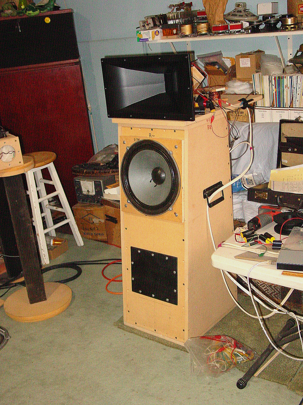
| PHOTO 1
The Usual Suspects |

|
| PHOTO 2
The rear chamber. The piece with the rounded
corners hole is the spacer. With the speaker front loaded, the
speaker gasket is just about 1/2mm above this plate, allowing a seal
when the horn is bolted on The
internal volume is larger than the 8.5 cubic inches to allow for
the wool to be stuffed in. This was deemed necessary as the box is
square, 3.25" on the sides. This corresponds to a wavelength
of 4187hz. Of course, the presence of the magnet assembly may have
prevented that Accounting for magnet
assembly displacement, the internal volume of the back chamber is about
15 cubic inches |

|
| PHOTO 3
The speaker gasket is about 1/2mm above the
surface of the spacer which provides a good seal to the horn
flange. A gasket of 1.5mm thickness was added to the
speaker gasket to increase the distance between the annulus and the horn
flange. This will allow for a 1mm excursion at 250hz, which is an
octave below the crossover filter and will produce an SPL of 87.3dB at
250hz The total volume, Vfc
between the surface of the cone and the horn flange is now 1.5 cubic
inches |

|
| PHOTO 4
The crossover is first order 2-way and the
polarities of the speakers are reversed with respect to each other
This
isn't common practice for a first order crossover but the reason will be
explained later in photo 10 |

|
| PHOTO 5
This was placed here just to have a look-see into
the horn. the woofer is a Wharfedale W12RS in a 3 cubic feet
sealed enclosure
Clicking on these last three photos, 5, 6 and 7
will produce a larger image |

|
| PHOTO 6
Just to show the whole test setup |

|
| PHOTO 7
This is the high frequency speaker without the
horn. This will be explained later in the conclusion section |

|
| PHOTO 8
This is the current rear chamber. The red
rectangle is the front baffle, onto which is front loaded the speaker.
The blue outlined rectangle above it is the spacer. The speaker
gasket rises above this by about 0.5mm to provide a seal to the
horn flange, which is the top rectangle |

|
| PHOTO 9
The red area is the proposed additional spacer
onto which would be placed a ring, shown by the inverted
triangles. the blue area is the same size as the horn throat
The idea was to decrease the front cavity volume
but that idea went to hell in the proverbial handcart, PDQ. (Pretty Darn
Quick) The volume would have been reduced by a about only 20% because
the additional volume of the blue throat would have partially offset the
volume reduction of the ring
A phase plug (green) can be added to further
reduce the volume but this would have to be designed in conjunction with
the red ring encircling the throat to obtain the correct throat area,
meaning a circular ring throat. This method was used in some ring
radiators. One that comes to mind because I had a pair and swapped
them with a musician for the ElectroVoice T-350 units is the JBL-075
tweeter (aka ring radiator)
Considering this, it was deemed to be a waste of
effort. It was decided to carry on with the original design and let my
ears do the critique followed by the CLIO, in that order so as not to be
biased by a response curve. |
 |
| PHOTO 10
The final crossover. A second order was
considered but this worked very well. Besides, it was easier to
juggle the component values.
Juggle?? After seeing the initial horn
response with a wide peak of several dB between 400hz and 800hz, and
knowing the woofer output would exacerbate that, it was decided to
spread the crossover points (Juggle)
After several attempts, a low pass of 5mh in the
woofer and a high pass of 5.6uf in the upper section, the
red response curve of fig 1 was obtained. Initially, the
system honked. So the crossover points were spread apart, first
starting with the woofer, then the tweeter. When the honking
stopped, a response curve was run and tweaked a little further in an
attempt to smooth the response between 500 and 2khz. See fig 3
This didn't have the effect I desired so the
tweeter polarity was reversed, going from the black trace to the red one
in fig 1
The grey trace at the bottom is the THD, less than
1% above 100hz |

|
| PHOTO 11
The added flange which made no difference
The purpose of this is described in the section
titled "Mouth Reflection Dip" at the bottom of this page
|
 |
The CLIO Results
| FIGURE 1
1w1m 5mh 5.6uf BLK = TWT norm pol;
RED = TWT rev pol; GREY = THD
It was later discovered that the dips at 450hz and
600hz and the rise centered at 750hz can be considerably reduced by elevating the horn by about 6
inches or moving it back by the same
This dip at 600hz is reminiscent of what Klipsch referred
to as a mouth reflection dip. This will be explained at the bottom
of this page.
Click on pic for larger image
|

|
| FIGURE 2
This figure was removed but the cell was left to
avoid having to find and correct references to subsequent figs after
renumbering them
|
|
| FIGURE 3
1w1m RED = horn only; GREY=THD
This shows the response of the horn loaded speaker
only, no woofwoof. The signal was electronically second order filtered
at 200hz to
control diaphragm excursion. That is one reason for the rapid drop
below 200hz. Another would be the small box volume
The high THD in the lower register is likely due to the
excessive loading of the very small box. The optimum volume for a
smooth response to 168hz is 63 cubic inches, according to BassBoxPro. However,
no mention is made of distortion. This box about 15
cubic inches giving a smooth response to about 191hz, the knee of the
filter, -3dB
Considering displacement of air due to the stuffed
wool, the diaphragm excursion at low frequencies, however small, would
cause deformation of the diaphragm. The wool was added to suppress
resonances at the higher frequencies when the wavelengths of those
frequencies approach the internal dimensions of the chamber
The back chamber volume was recently reduced to 7
cubic inches by adding 4 wood blocks around the rear inside
perimeter. The wool was removed. No noticeable change,
graphic or aural, was detected
Click on pic for larger image
|
 |
| FIGURE 4
Z RED = horn box w/o horn; BLK = with horn
One might expect to see the resonant point rise
due to the horn throat being slightly smaller than the speaker cone
area. An attempt at explaining this is adjacent to fig 5
The vertical scale in fig 5 is different
Click on pic for larger image
|

|
| FIGURE 5
RED=Z open air
ORANGE=Z in 15 cubic inch box
Black=horn attached to box
A speaker mounted in a sealed enclosure will
exhibit a higher point of resonance. This is due to the spring
effect of the air trapped behind the cone. The impedance magnitude
is also reduced as in the orange curve
This phenomenon has been mentioned in technical
papers but the writer, probably an engineer
assumed the reader would also be an engineer. I'm not, so it had
me pondering this for awhile since at first glance it is
counterintuitive. A suitable, although not necessarily complete or
correct, explanation came up and
lit the proverbial light bulb

The resonant point lowers with the horn attached
(black)
possibly due to the air in front of the cone, not being trapped,
moves through the horn throat
This will also lower the impedance
as can be seen due to the restriction of cone motion but that moveable air is also seen as an added mass on
the cone, which will lower the point of resonance. With cone motion
blocked, the impedance will approach the DC resistance but never reach
it due to the reactance of the coil.
Click on image for larger view
|
 |
|
Conclusion
OK. So it looks good on
paper but how does it sound and is there much, if any, difference between
direct radiating and horn loaded? Keep in mind that the following
may contain some subjectivity regardless of how much effort is put into
maintaining objectivity
A higher output than that
of the direct radiator was expected but not realized.2 This is
thought to be due to the very wide bandwidth for which the horn was
designed. One way to determine the suitability of a speaker for
horn loading is by the EBP, )Efficiency Bandwidth Product) which is
stated as, EBP=fs/Qes (Eq-12)
The general consensus is that for sealed enclosures, EBP should be less
then or equal to 50 and for vented enclosures, greater that or equal to
100. This particular unit has an EBP of 17, making it
suitable for a horn since a horn uses a sealed enclosure behind the
speaker, Vb
Also, the slightly smaller throat will have a negative
effect on the lower part of the band, imposing a heavier load on the
diaphragm. The response in fig 3 was obtained without the throat
adapter, using the 2 inch throat of the horn. Initially, it was
thought that this would negatively affect the extreme high end but that
proved to be incorrect, (red trace, fig.1). The bump in the band
between 400hz and 1300hz (fig 3) was flattened by spreading the
crossover points, now 300hz and 2khz, first order. A smaller front
cavity and maybe a phase plug (photo 9) may have helped increase
the efficiency of the highs. That modification hasn't yet been
shelved. The larger back chamber volume may also have contributed
to this lower midrange rise. The current back chamber volume will
be reduced by adding wood blocks inside to get to the ideal 7 cubic
inches from the current 15 cubic inches. It was originally thought
that the highly packed wool in that chamber would achieve this.
Replacing the wool with wood will verify that
Despite the lack of
increase in efficiency, what was noticed was the presence of the mids.
It should be noted that efficiency and bandwidth are inversely
proportional. Since the response is relatively linear, (red trace, fig 1) it was
noticed that the horizontal dispersion widened. Listening tests showed that the
listener's position can move as much as 45o off axis before
an loss of the very high frequencies could be noticed. This wasn't
tested because of having to move the coffee table plus the stuff stashed
under it
A couple of friends gave
it a listen and were astounded at how well they sounded upon entering
the room. They were, at that point, about 12 feet from the
speakers and about 45o +/-5o off axis. Both
agreed with my feeling that it sounded a little bright on axis but that
was at better than 95dB SPL at several feet
So, in short, better
horizontal dispersion was obtained with no loss or gain in
efficiency. A satisfactory tradeoff
|
|
FIGURE 6
These response curves are those calculated by Bas
Box Pro, v6, re: the 3FE22. They show the normalized response in an
optimum sealed enclosure of 63 cubic inches (red) and the box for the
horn, (orange) of 15 cubic inches and (yellow) 7 cubic inches. This comparison was
run to find out if such a reduction in volume would produce a bump.
There appears to be a 3dB to 4dB rise around 400hz, (orange) which may be a
problem. The yellow shows a 6dB rise in that region. With a
first or second order filter at 500hz, the rise at that frequency would be
lowered by 3dB, the knee of the filter

|
| The Mouth
Reflection Dip
Paul Klipsch describes this in very great
detail, along with the solution in his paper titled "A New High
Frequency Horn" 3
Briefly, a dip in the response of about
7dB was noticed at 480hz. The solution was to install the horn
onto a flange of area three times the horn mouth area. This also
resulted in being able to halve the mouth of the horn, thus shortening
it by close to 3 inches. The flange (baffle) maintained a close aspect
ratio of the horn mouth dimensions.
The dip noticed in my design may be
the result of that or caused by the horn's proximity to the woofer.
Fig 6 shows no dip at 600hz with the woofer disconnected. Adding a baffle of 3 times the mouth area
and the same aspect ratio to this horn made no difference. The
baffle measures 23" wide by 15" high Photo 11
|
|
Footnotes
1 Consider a straight axis bass
horn for the Faital 15PR400 with a modest low frequency cutoff of 47hz,
like the Klipschorn. It would have a mouth diameter of 24 feet and
have a total length of 13 feet. One must look with admiration upon
the Klipschorn with its total length of about 4 feet
2 Suitability of Low frequency
Drivers for Horn Loaded Loudspeaker Systems - Richard Small Audio
Engineering Society (AES) May 1977
3 Submitted, June 24, 1963, IEEE
Transactions On Audio, pages 201-206 |
| Deviations
From Generally Accepted Horn Theory
FIGURE 7 (click for
larger image)
Many horns designed for midrange or
full range cone speakers seem to deviate from horn theory, especially
at the throat. For a circular horn, it seems to be common
practice to fit the loudspeaker at the throat which has a diameter
equal to the inside diameter of the speaker's front gasket. If
square or rectangular, the square may have an area equal to that of
the above or the effective cone area. If the corners of this rectangle
or square protrude beyond the circumference of the speaker, the
rectangle or square will be adjusted to fit, resulting in a smaller
area which, in actuality, me be closer to the correct throat area.
The crude figure below gives an example
of such a design; it assumes a 6" speaker. The length and
mouth diameter is approximated from such designs seen online. It
assumes an exponential horn although they could be tractrix, which
will result in a shorter length but the mouth area will be much the
same as that is determined by fc the low frequency
cutoff. This example uses inches. The following is more
readable than the chicken scratch in the figure below, from the top
We are given the throat diameter as per
C.R.Hanna, D as 4/b or l/p
and b=4pfc/c To the
right of that is stated a 6" speaker being used with a 5"
horn throat diameter. Below that, is Keele's equation for throat area
expressed in T-S parameters, St=2pfsQtsVas/c
Under Parameters we have the
throat diameter and mouth diameter, Dt and Dm
respectively and below them we have throat area and mouth area, At
and Am respectively, followed by the horn length, Lh
(which, to maintain the nomenclature previously used, should have been
written as HL )
Next we divide the mouth
area by the throat area and get 16.028, which is equal to ebx
. Taking the natural log of both sides, we get bx=2.774 and
since the horn length, x=24", we get b=0.1156.
Now, using the equation given above for b, by transposition, we get fc=bc/4p=125hz.
(The wavelength of 125hz is shown under that equation). From this
we can calculate the mouth diameter to get 34.6" which is 1.73
times larger than originally estimated. This method is similar to
a process known as reducto ad absurdum, whereby an initial
statement being assumed to be true is proven false, assuming, of course,
that the logic between is without fault.

Despite the deviation from accepted
throat area, not to mention the cavity volume in front of the c one,
these deviant horns can sound damn good.. The horn used for the
Faital is also a deviant from horn theory d sounds damn good.
Admittedly, these circular horns look a whole lot better and if they
sound as good as they look, which I don't doubt, they have to sound
nothing less than awesome. The biggest problem with circular
horns is their construction, not to imply that a rectangular horn is
easy. |
| The following figures
are spectra taken at various frequencies. The left column are
those of the HF speaker in its back chamber of 7 in^3 without the horn
and the right column are with the horn. All are taken at 1w1m, the
power being calculated at the impedance of the system at that
frequency. All are measured with the woofer and through the
crossover.
These spectra were placed here in an attempt to
"see" one of the reasons the horn sounds different than the
direct radiator.
The hash at the left is ambient noise, most likely
from tha AC unit. Note in figs 9 & 16 the missing bump in the
octave between 50hz and 100hz, probably due to the AC unit shutting
down. |
| FIGURE 8

|
FIGURE
9

|
| FIGURE
10

|
FIGURE
11

|
| FIGURE
12

|
FIGURE
13

|
| FIGURE
14

|
FIGURE
15

|
| FIGURE
16

|
FIGURE
17

|
| FIGURE
18

|
FIGURE
19

|
Back to the
loudspeaker main page
Table of
Contents