An EICO Odyssey


This page was inspired after noticing an almost complete lack of info on these units in an AudioKarma EICO forum. Uploading all this info into that forum seemed to be a daunting task considering my years of experience using Microsoft's Front Page Web Management Tool since 1997.

Hopefully, the data here will be useful to someone.


My EICO Story

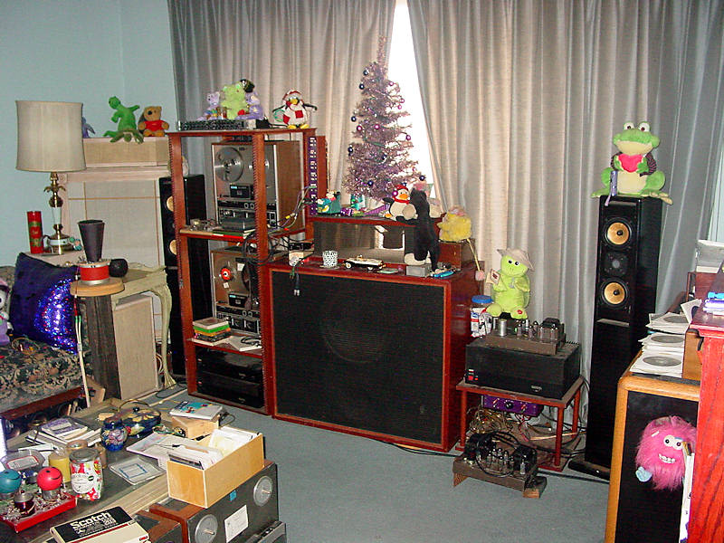
It started in August of 2026 when it was noticed that the bass sounded fuzzy. Initially, it was thought to be the open cell foam annulus on the W15FS, a 1950's Wharfedale woofer. That 3-way system was built by a half-brother in 1957 and was given to me around 1972. The bass enclosure is a 10 cubic feet bass reflex, recommended by Wharfedale.  Click image for a larger one.

Anyway, the cabinet was pulled away from the window and the back removed. The woofer was OK. It was removed and taken to my workshop where it was rub-buzz tested. The foam was intact and the cone hadn't drooped in the front which was common with open cell foam annuli. It was actually recommended to rotate the woofer every year.

After buttoning up the cabinet, it seemed to work ok for another hour. However, after the last recording finished, the system was on for another hour or so, during which the 6X4 gave up its ghost. This was not noticed as there was no music playing, so the system was turned off  and the problem was forgotten.

Come late September, the system was fired up again. There was little volume output; the volume control had to be rotated full clockwise to get a decent level. Something was obviously amiss.

The easiest thing to address was the power amp. It passed every rigorous test to which it was subjected. Then came the pre-amp. The first thing checked was its output level and that was found to be very low, less than 100mV with 1 volt applied to the input.

The first thing looked at was the AC output of the power transformer. It checked OK at 300-0-300 VAC. The the output of the 6X4 rectifier was around 95VDC but should be about 335VDC.

The schematic has a table of some 27 points to check for dc resistance with respect to two different common points. All checked out well within their +/-15% tolerance.

That 6X4 was that which came with the unit when purchased on eBay in 2006, meaning it was older than 20 years. The unit was working when purchased.

So, a 6X4 was purchased along with a 12AX7 and a 12AU7.

The tubes arrived a day earlier then promised. After inserting the 6X4, the HF61 performed flawlessly, actually much better than expected. Details are presented further down.

It should also be noted that this HF61 has its own tubes' plates power supply; it does not depend on using the octal power socket. This is a good feature as my preamp and power amp are separated by around ten feet. Such a long line carrying some 370 VDC doesn't seem like a good idea.


First, the usual suspects


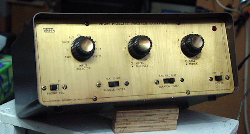
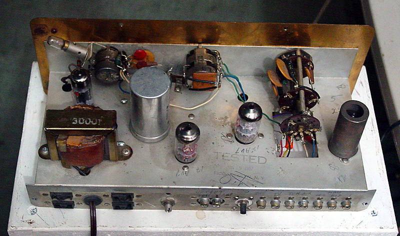
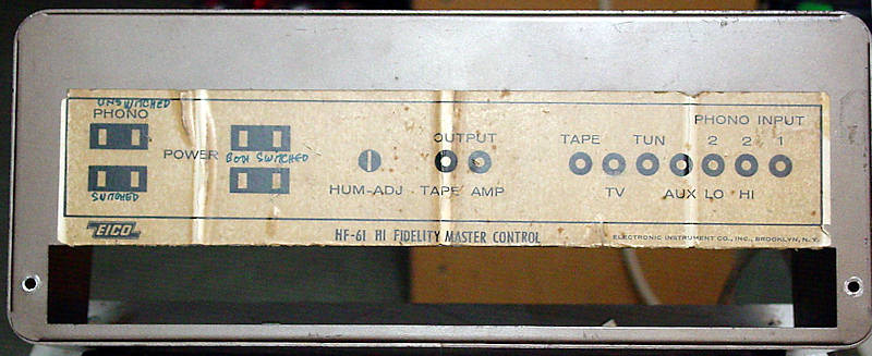
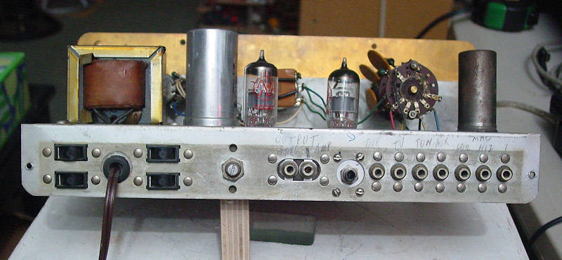
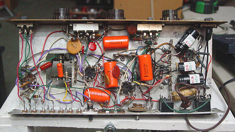
The HF-61 preamp

Photo 1

Photo 2

Photo 3

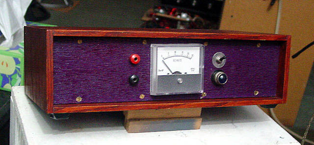
The input jack to the right of the horizontal pair, tape & amp outputs is for the 12VDC supply to the tubes' heater filaments.  (photo 14)

Photo 4

Photo 5

All but one of the paper tubular wax coated capacitors were replaced as were the power supply filter caps. With the caps and tubes removed, close to all resistors were isolated and easily checked with an ohmmeter. Several were replaced. Resistors that were Ok and connected to socket pins were left alone to avoid damaging those delicate pins on the tube sockets.

Neither of the power amps were altered as they performed quite satisfactorily. Sometimes, "If it works, don't fix it" is a good philosophy to follow. At the time of this writing, both power amps still perform satisfactorily, some 15 years after their purchase.


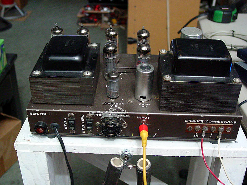
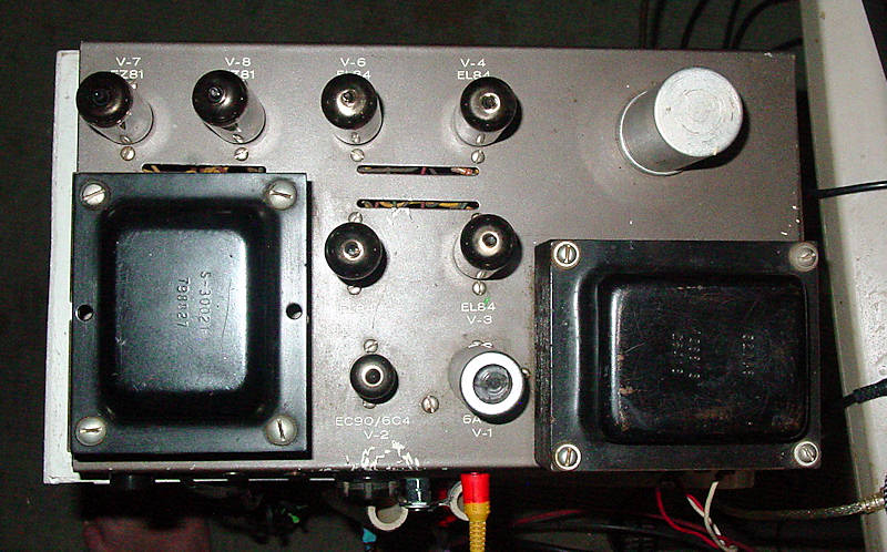
The HF-30 8 tube power amp

Photo 6

Photo 7

Photo 8

Photo 9

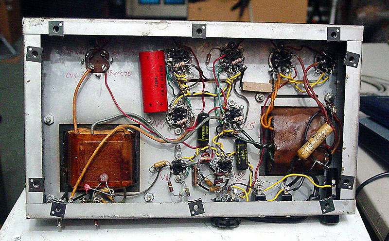
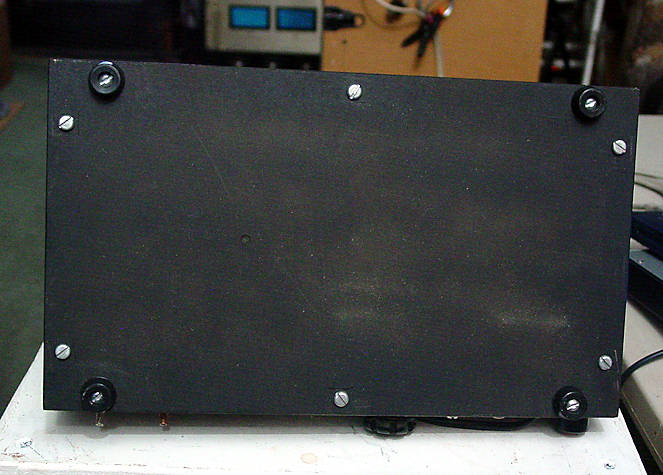
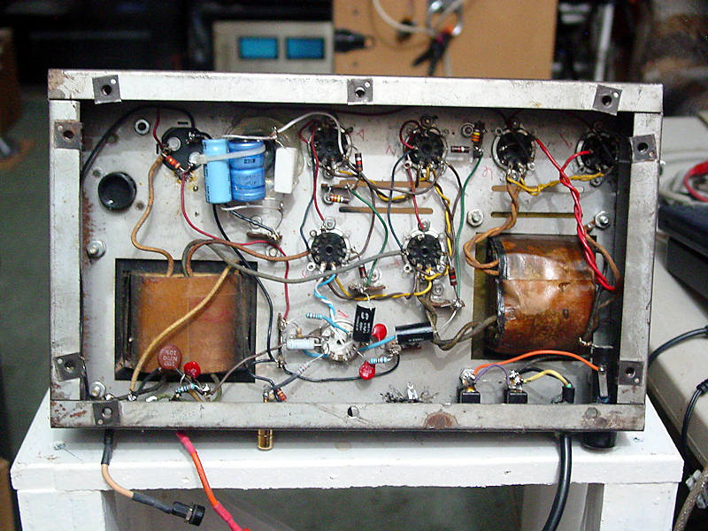
When purchased, the amp had no bottom cover, so I made one.


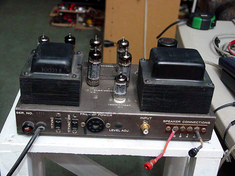
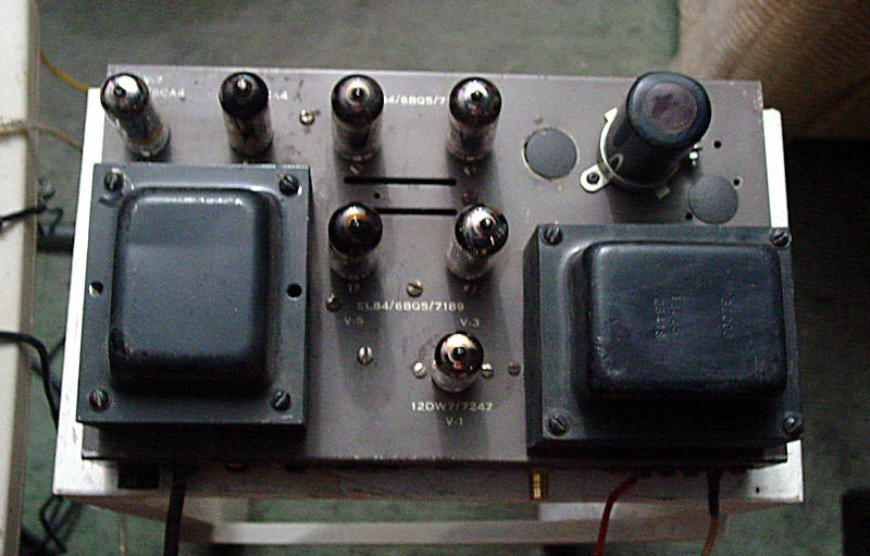
The HF-30 7 tube power amp

Photo 10

Photo 11

Photo 12


The technical stuff

HF30  8 tubes

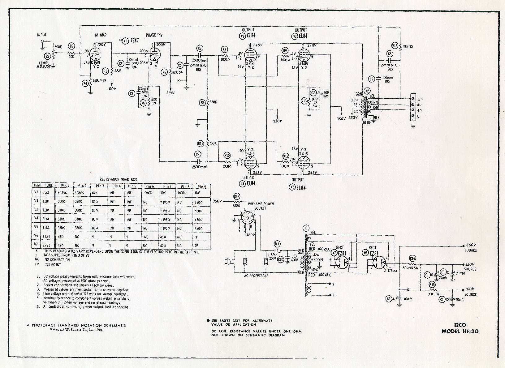
FIGURE 1

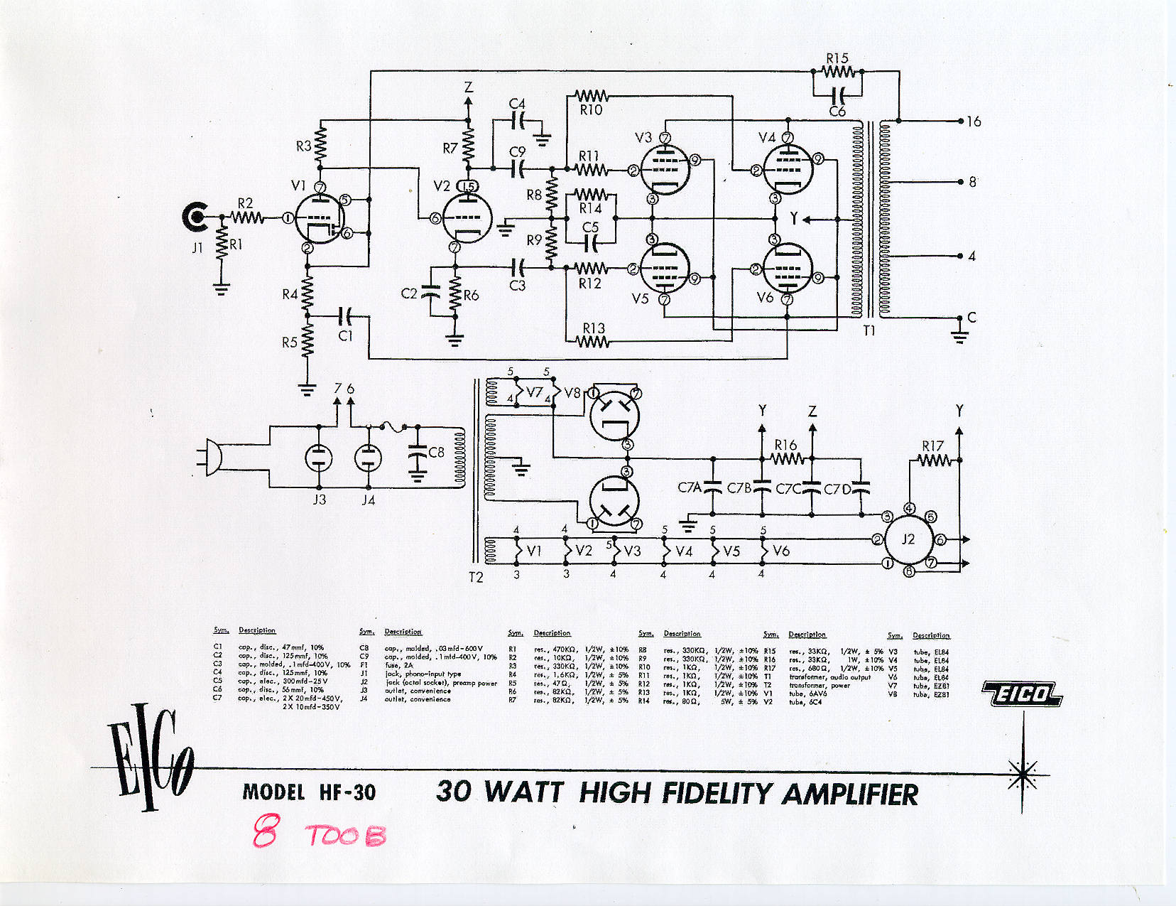
The schematic. Click on the image for a larger and printable one

Photo 13

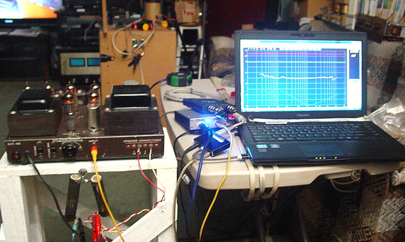
HF-30 8 tube on the bench. The two hanging resistors are 4W 60W each and wired in series.

On the left of the computer is the PicoScope (top) and the CLIO. The blue pilot light on the CLIO is bright enough to use as a spotlight. The little black box in the front is a powered USB hub.


FIGURE 2

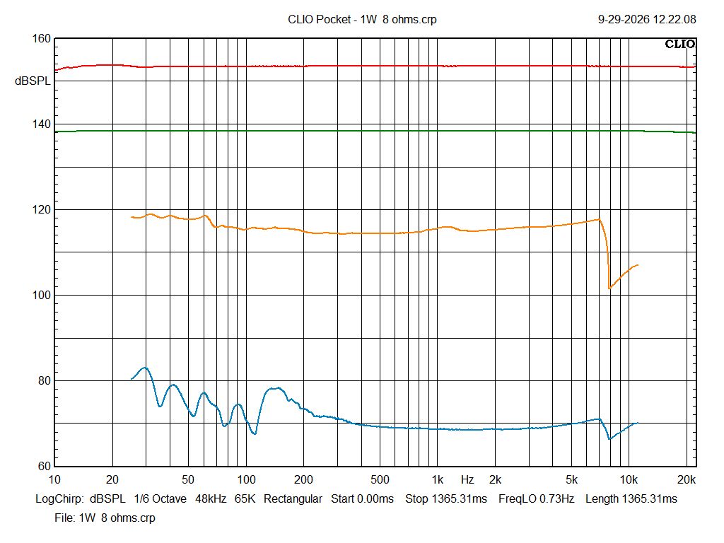
GREEN 1W into 8W BLUE THD      RED 32W into 8W ORN THD

Click on the image for a larger one. This will show the colors much better.

Input of 0.192V yields 1W into 8W (2.83V)

Input of 1.15V yields 30W into 8W (15.49V)

gain = 22.6dB


At 1W power output, THD above 300hz is around 0.031% and at 150hz, it's around 0.1%

At 32W power output, THD is between 1% and 1.6 between 32hz and 7khz, after which it drops rapidly for some unknown reason. At 150hz, it's 1.6%

The dB to % conversions were derived from sengpeilaudio


This amp runs hotter than the 7 tube unit. The power transformer was measured around 136.3F after 3 hours. This is hot enough to force the palm of one's hand to be quickly removed after one second, or less.

This is attributed to the heater filaments of the tubes.

Vh and  Ih are tube heater voltage and heater current, resp.

EL84/6BQ5 Vh=6V Ih=0.76A There are 4 such tubes drawing a total of 3.04A

EZ81/6CA4 Vh=6V Ih=1.0A There are 2 such tubes drawing a total of 2A

EC90/6C4 Vh=6V Ih=0.15A

6AV6 Vh=6V Ih=0.3A

That's a total current drain of 5.59A which equates to 33 watts.


HF30  7 tubes

FIGURE 3

HF-30  7 tube schematic.  Click image for larger and printable one


FIGURE 4

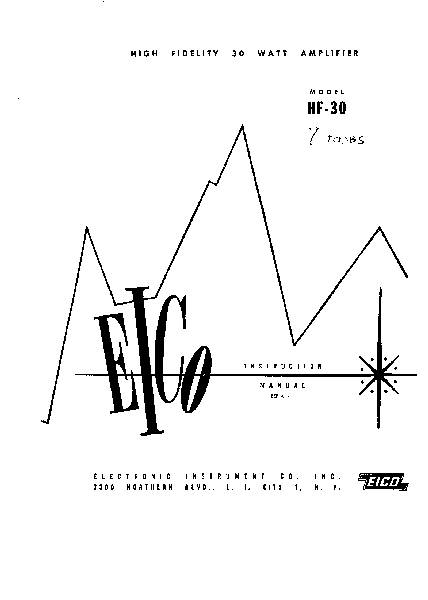
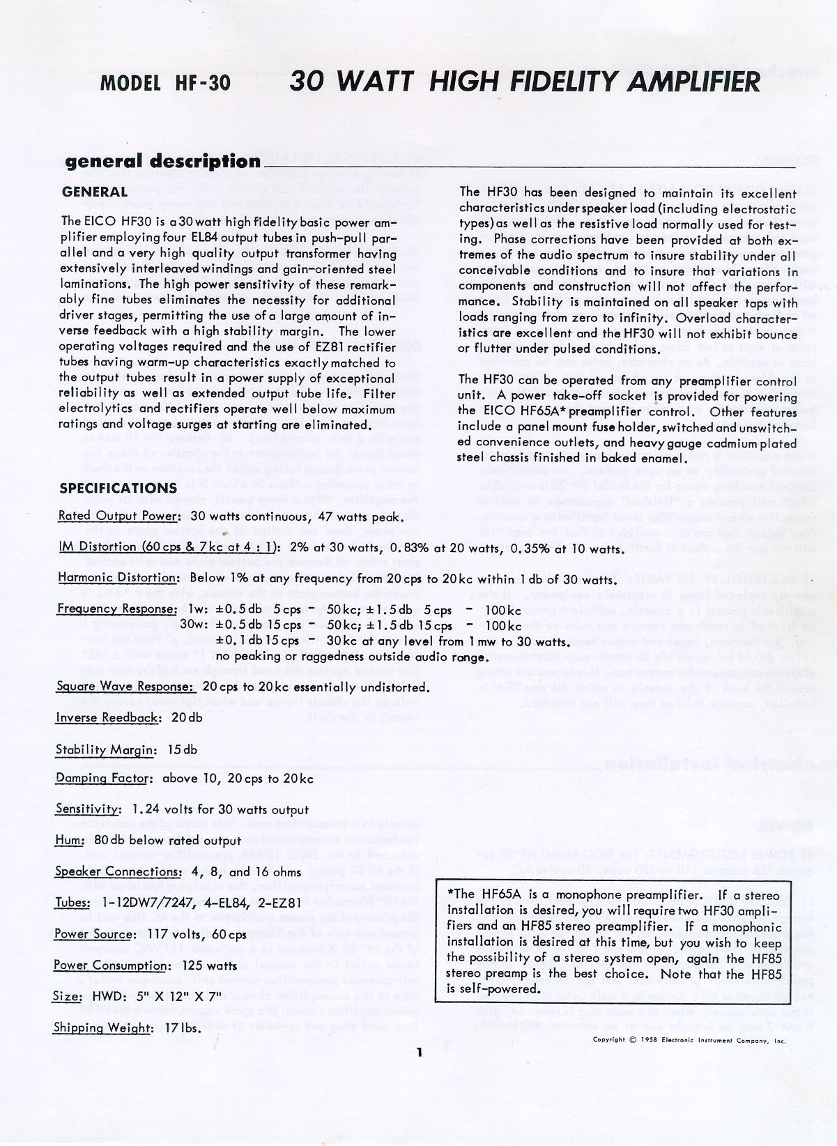
Figures 4 and 5 are the cover and spec sheet from a complete kit assembly instruction book. I have no idea from where it was acquired; it's one of those surprises found in my data treasure chest.


FIGURE 5


THD measured with the CLIO harmonic distortion analyzer

CLIO sine wave genny 0.008% THD+noise

Input of 0.218V yields 1W into 8W  with 0.146% THD

Input of 0.8V yields 13W into 8W (10.25V) with 0.3% THD

Input of 0.815V yields 13.6W into 8W (10.43V) with 0.5% THD

Since THD rises quickly with an output of  >13W, this was considered to be the maximum. This can easily be seen on a scope when the top of the sine wave begins to flatten.

gain = 22dB


Since this unit produces 13W instead of 30, it seems quite in the realm of possibility that the amp was modified to single ended.

The power transformer temperature after 3 hours was measured as 128.6F. I was able to keep the palm of my hand on it for about 10 seconds. The tube heater filaments draw about 25 watts.

The above is much the same as the original 7 tube unit with exception of the power output. For more info on the original 7 tube unit, see the spec sheet

More data on this highly modified unit was deemed useless as this is probably the only one of its kind.


HF61

Voltage after 6X4 tube replacement

AC line  121.5 VAC

At the 6X4 socket without the tube:   pins 1 or 6  320 VAC with respect to chassis

   At the 6X4 across pins 1 and 6   636 VAC

At the 6X4 socket with the tube inserted:   pins 1 or 6   305 VAC with respect to chassis

At the 6X4 socket:   pin 7    373 VDC with respect to chassis   


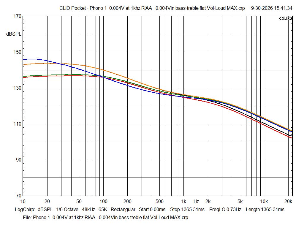
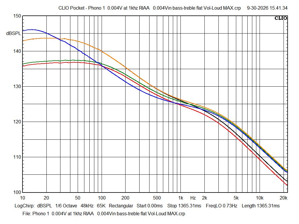
These equalization response curves were obtained with 0.004V input and with the controls set as follows.

Level and Loudness at full clockwise; Bass and Treble at Flat, mid rotation, 12 o'clock, high noon.

Rumble and Scratch filters OFF.

The colours refer to  COL-red;  LON-green;  RIAA-black;  AM78-orange;  EUR78-blue

Click on either one for a large format which will clarify the colours.


FIGURE 6


FIGURE 7


AUX 0.25Vin Loud5 Vol4 Bass2.5 Treb1

FIGURE 8

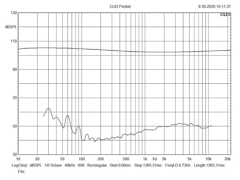
This set of curves was obtained with the controls set where I usually set them for listening through that vintage Wharfedale 3-way. They are usually set with the Level at 12 o'clock, Loudness at 3 o'clock, both filters OFF. Also, this set was obtained with 0.25V into the AUX input . This is where I feed my CD player or reel to reel tape recorders using their headphones' outputs.

The response could have been made flatter, damn near a straight line by tweeking the Level and Loudness controls but they would be set at positions difficult to remember. The difference in sound would have been negligible.

Besides, I prefer to listen to the music, not the loudspeakers.

The lower curve is THD. the percentages at the designated frequencies are  frequency/THD %

30/1.41   40/0.35   50/0.18   60/0.10   70/0.03   80/0.11   90/0.003   100/0.001

The dB to % conversions were derived from sengpeilaudio


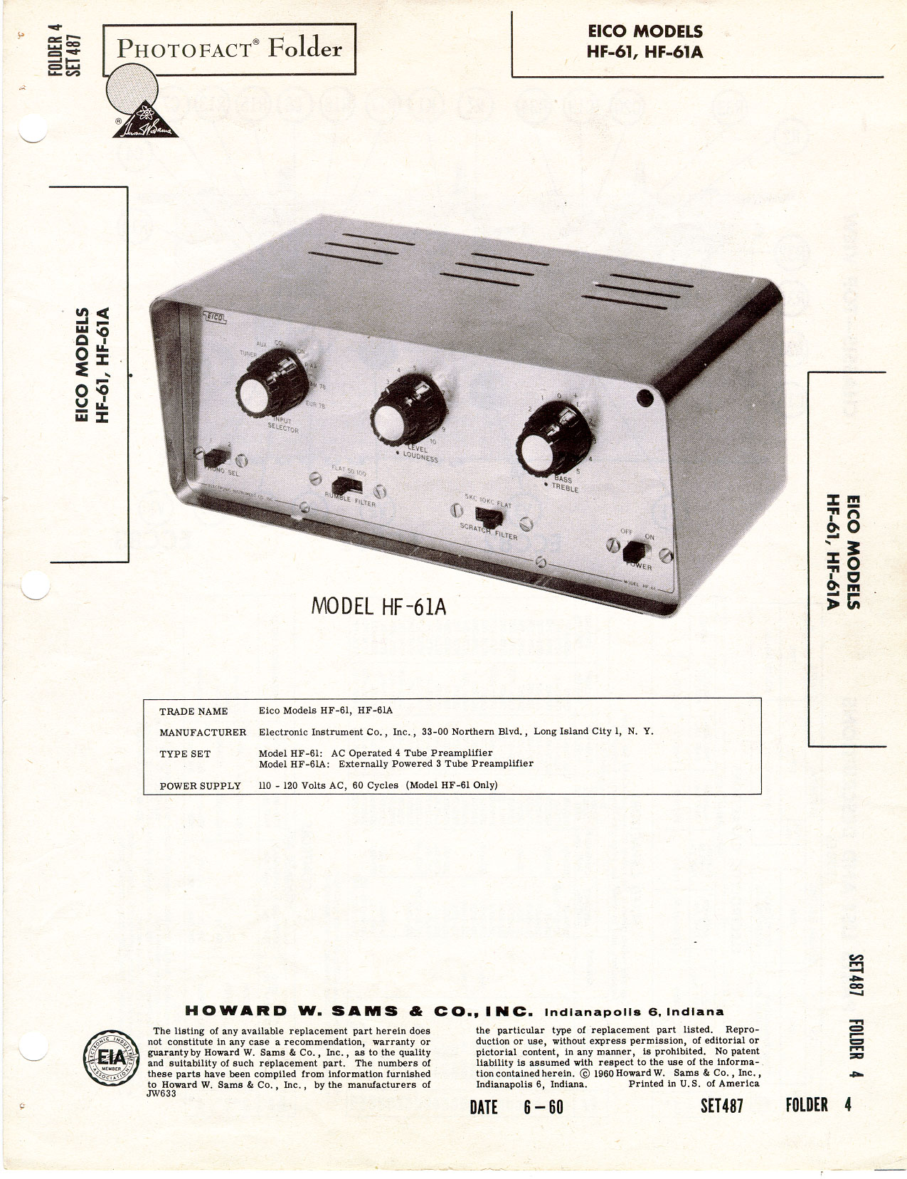
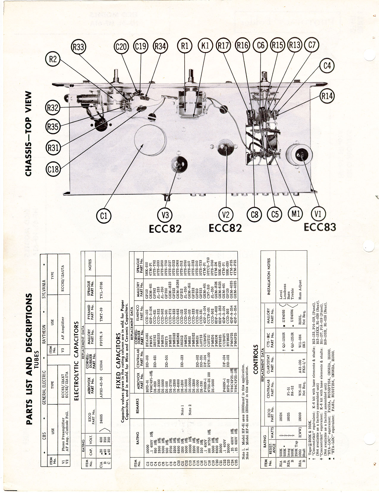
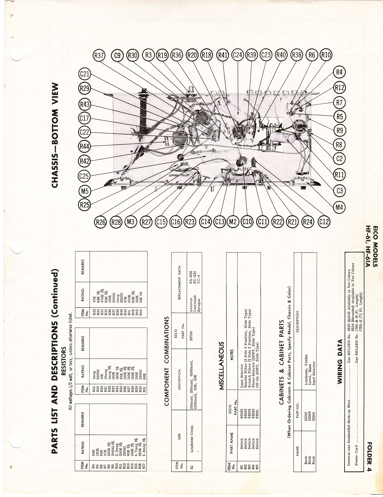
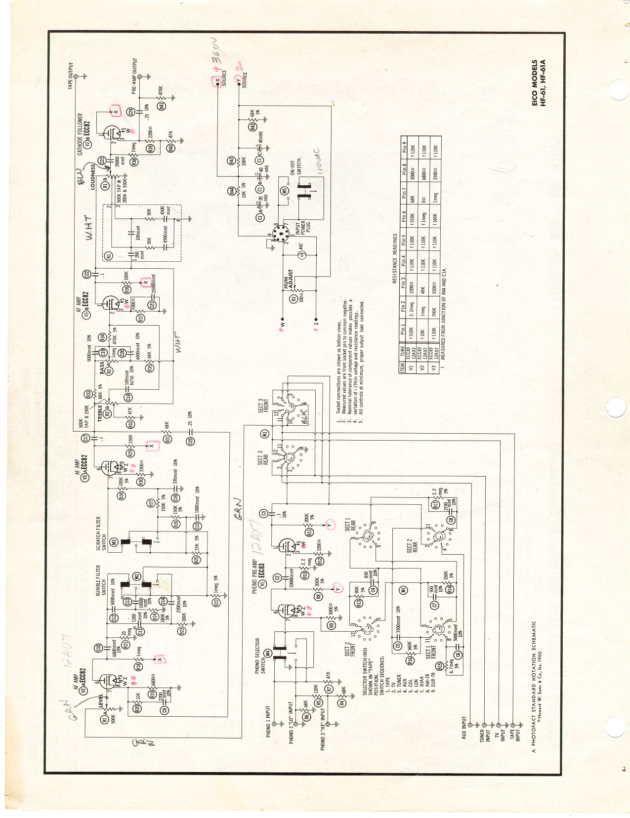
The following is a complete Sam's Photofact of the HF61 schematic. My apologies for their not being in pdf format. They are in jpg format, high resolution and ready for printing. Click on each for a large format.

Somewhere in this forum I think I saw a link to the pdf format but now I can't find it.


Page 1 of 4


Page 2 of 4


Page 3 of 4


Page 4 of 4


MISCELLANY


The following is a collection of projects done over the years regarding the above units.

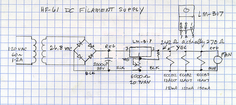
The first was an attempt to remove all the hum, which was close to inaudible with no music playing and the bass boosted and be within a few feet of the woofer. However, I saw that as a challenge. After designing a 12VDC power supply to power the pre-amp tube filaments (heaters), the result made no improvement. It may be weak shielding of the 12AX7 and or the 12AU7 tubes from a stray field from the power transformer. Since only one tube socket, that of the 12AX7 had a shield, adding a shield to the other tubes meant replacing the sockets or running a ground wire from the shields to a known good ground, not the chassis.

A few years later, that DC supply was removed to make room for another component.

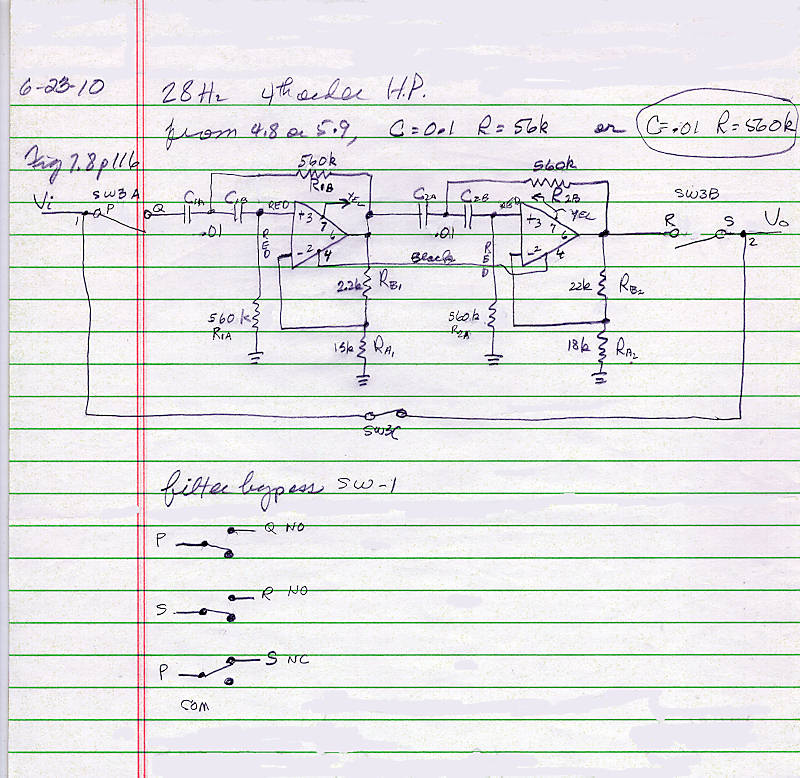
Then another S.W.A.P. (Scientific Wild Ass Project) came to mind; a low frequency high order active high pass filter. Well, that was an exercise in futility as it had no effect. Spectrum analysis showed the major frequencies of the hum were at 60hz and 120hz and building a pair of high Q active notch filters wasn't appealing.

Again, this hum was close to inaudible with no music playing and totally inaudible with music, even with a moderate bass boost.

Anyway, here's the 12VDC supply and the high pass filter

Photo 14

12VDC heater filament power supply and schematic


FIGURE 6


FIGURE 7

28hz 4th order high pass filter


Back to the Table of Contents

Back to the loudspeaker main page